In the fab shop we choose thickness by matching the part's required stiffness and load path to the nearest standard stock gauge that our lasers, punches, and press brakes can process without special tooling. For most enclosures and chassis the starting point is 16- or 14-gauge mild steel; anything thinner is checked for oil-canning risk and anything thicker is checked for tonnage and spring-back. That practical filter is the core of any useful sheet metal thickness selection guide used on the production floor.

Thickness is never chosen in isolation. It directly sets the minimum bend radius, the punch or laser parameters, the required brake tonnage, and the final part weight. Mild steel from 0.8 mm to 3 mm (roughly 22- to 11-gauge) covers the majority of production work. Aluminum is typically run thicker than the equivalent steel gauge to recover stiffness because its modulus is lower. Stainless usually stays in the same thickness range as mild steel but demands more forming force and larger bend radii. Once the material and thickness are fixed, the available tooling library and machine capacity decide whether the job stays on standard process or needs a special setup.
Why thickness decisions show up first in laser power, tonnage, and spring-back
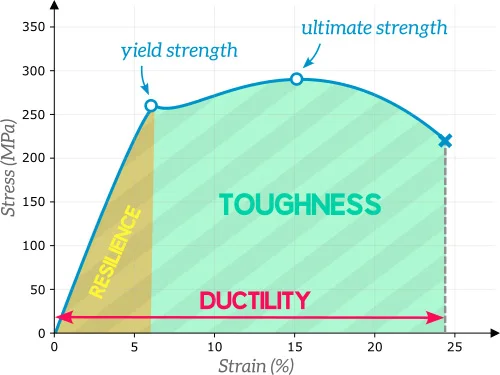
Every increase in thickness raises the force the press brake must apply and the power the laser must deliver. A jump from 1.5 mm to 3 mm roughly doubles the bending force and can push a job from a standard 80-ton brake onto a larger machine or require a slower stroke. Spring-back also grows with thickness and with higher-strength alloys, so the same angle program that works on 1.2 mm steel will under-bend on 2.5 mm stainless. On the laser, thicker plate slows feed rate and increases heat input, which can open kerf variation and edge dross. Weight rises linearly with thickness, affecting both material cost and shipping. These process limits force the thickness choice long before the part reaches the customer.
If the thickness is left uncontrolled the shop sees predictable problems. Too thin and the panel oil-cans under its own weight or under light assembly loads; doors and covers warp and gaskets lose compression. Too thick and the part becomes expensive in material, slow to cut, hard to form without special dies, and heavy enough to change handling and freight costs. Near the limit of available tonnage the operator must slow the cycle or risk incomplete bends. When the thickness also sits outside the standard stock list the material itself becomes a special order with longer lead time. All of these issues appear as either scrap, rework, or delayed shipment.

How the shop actually picks and locks the thickness in production
Process engineers start with the functional requirement—how much deflection is allowed under the stated load—and then look at standard gauges already on the shelf. For light electronic enclosures and covers, 1.0–1.5 mm (18–16 gauge) mild steel or the aluminum equivalent is the usual choice; it forms cleanly on most brakes and keeps weight low. Medium chassis, brackets, and industrial panels move to 1.5–2.0 mm (16–14 gauge). Heavy brackets, machine frames, and load-bearing chassis go to 2.5–3.5 mm (12–10 gauge) or thicker. Aluminum is typically specified 20–40 % thicker than the steel version it replaces if the same stiffness is required. Once the gauge is selected, the CAM review confirms that the chosen thickness still allows the designed bend radii, hole sizes, and flange lengths under the shop's normal rules (minimum radius ≈1×T for mild steel, larger for stainless and hard aluminum).
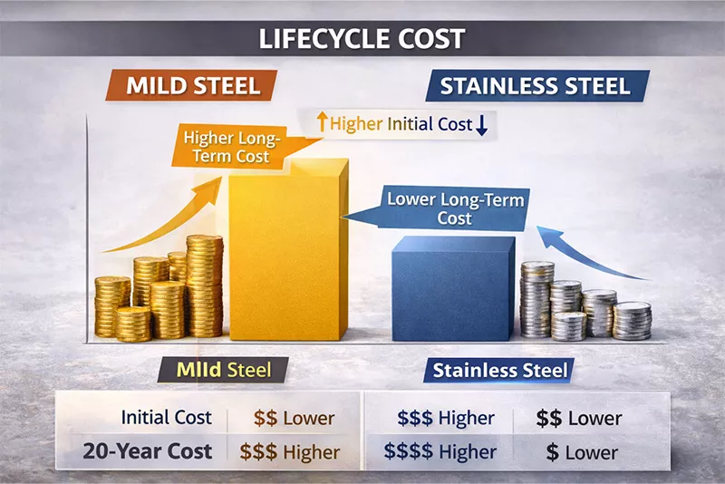
Cost is checked next. Material price rises with thickness, but so does processing time. A part that can stay on a standard 1.5 mm coil and be formed on an 80-ton brake is almost always cheaper than the same geometry forced into 3 mm plate that needs a larger machine and slower cycle. When stiffness is the real problem, the shop often recommends adding a rib, a return flange, or a simple emboss instead of jumping a full gauge; the geometry change usually costs less than the extra material and forming force. The final thickness is locked only after the nesting program, the available punch and die set, and the brake tonnage all confirm the job can run without special setups.

A short DFM checklist used on every new job is straightforward: confirm the thickness is a standard stock gauge; verify bend radii stay within 1–1.5×T for the chosen alloy; check that hole diameters remain ≥T; keep flange lengths long enough for the thickness; and decide whether a geometry stiffener can replace the next thicker gauge. Following these steps keeps the part inside the normal process window and avoids most thickness-related surprises.
When the shop will accept non-standard thickness and the trade-offs
Exceptions occur when the customer already owns tooling matched to a specific gauge, when the part must meet a regulatory minimum thickness, or when weight is critical enough to justify aluminum plate instead of steel sheet. In those cases the shop accepts the longer material lead time, the higher tonnage, or the slower laser speed and quotes the extra cost and schedule impact. Prototypes sometimes run on non-standard thickness for functional testing, but the production recommendation always returns to the nearest standard gauge that satisfies strength, formability, and cost together. The goal remains the same: choose the thinnest practical thickness that still meets the load and stiffness requirement so the part stays easy to cut, form, and ship.
Thickness selection is one of the earliest and highest-leverage decisions in sheet metal work. Getting it right at the design stage keeps the job on standard stock, standard tooling, and standard cycle times.