Most cost overruns in sheet metal do not come from exotic materials or complex geometry. They come from a short list of design decisions that force extra operations, scrap, or rework. These sheet metal fabrication mistakes show up repeatedly in DFM reviews and on the shop floor.
The part looks finished in CAD. Then the quote comes back higher than expected, or the first articles fail inspection. The root cause is almost always one of the issues below. Each one is avoidable if the designer accounts for real process limits instead of ideal geometry.
Material Waste from Poor Nesting and Non-Standard Blanks
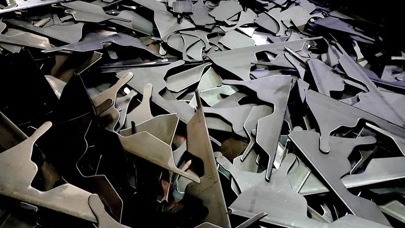
Designers often size parts to exact finished dimensions without considering standard sheet sizes. The result is large offcuts that cannot be used on other jobs. Nesting efficiency drops. Material cost climbs.
When multiple parts share a common thickness and alloy, slight dimensional adjustments can raise nesting yield from 60 % to over 80 %. That difference is pure margin. A 10 % improvement in material utilization on a high-volume job often exceeds the entire labor cost of the part.
The mistake is treating the blank as a freeform shape rather than a piece that must come from a rectangular sheet. Shops buy standard sizes. Anything that forces remnant waste or special sheet ordering adds cost that never appears in the CAD model.
Features That Exceed Available Process Capability
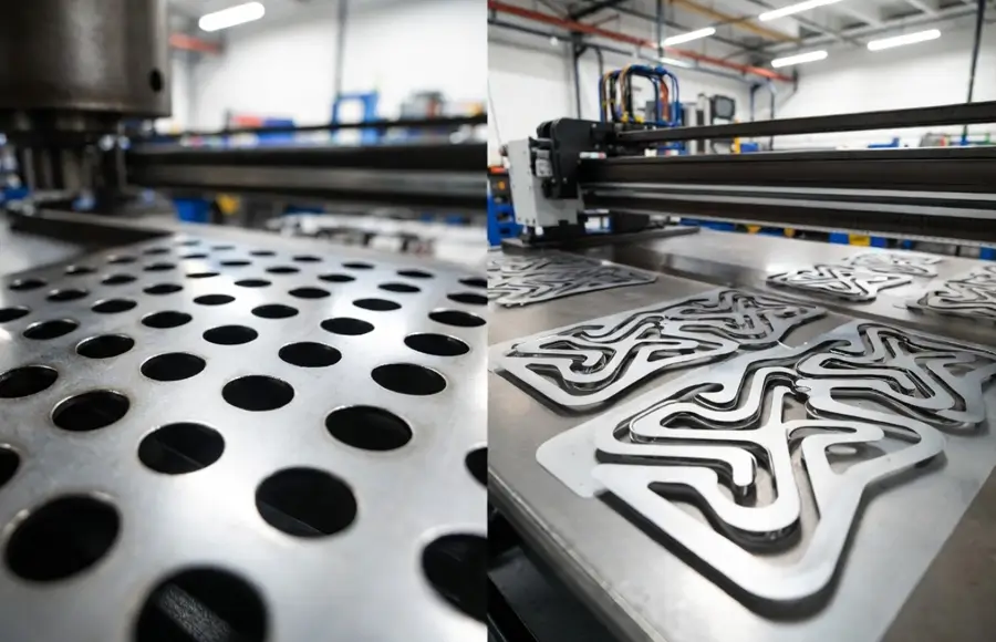
Designs that require laser kerf narrower than the machine can hold, or punch features smaller than the tooling inventory, force secondary operations. Sometimes the shop has to outsource a simple hole or slot. Cost multiplies.
Check the actual capability of the intended process before locking the model. Minimum feature size, minimum web width, and maximum aspect ratio are not theoretical limits. They are shop limits. A 0.5 mm slot in 2 mm steel may be laser-cuttable on one machine and impossible on another without a secondary EDM or milling step.
Engineers often copy features from previous designs or from solid-model libraries without verifying the current process window. The result is a part that looks simple but requires an extra setup or outside process that was never budgeted.
Incorrect Bend Radius Relative to Thickness
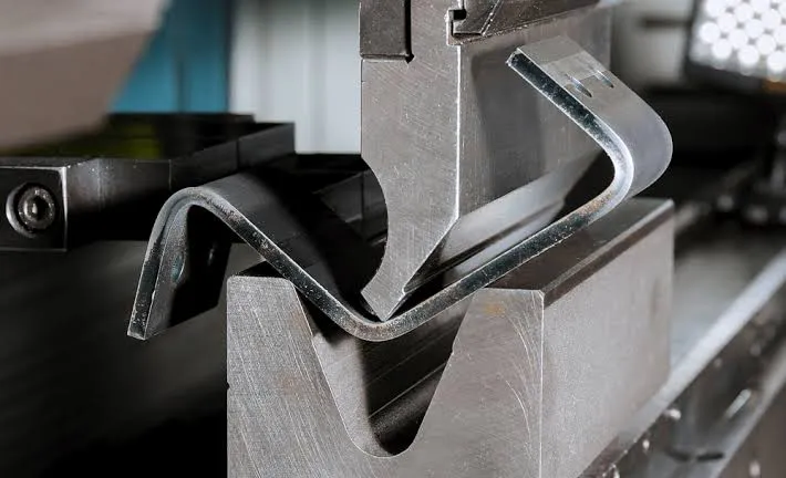
Specifying an inside radius smaller than material thickness is common. The press brake either cracks the outer fiber or requires a special die. Special tooling adds cost and lead time. Cracking adds scrap.
For most mild steels a minimum inside radius equal to material thickness works. Harder alloys need more—often 1.5× to 2× thickness for stainless or high-strength grades. Changing the radius in the model is free. Changing it after tooling is ordered is not.
The design choice usually comes from wanting a sharp look or matching a plastic part geometry. On the brake the material does not care about aesthetics. It only responds to ductility and the available die set. When the radius is too tight the shop either runs slower with higher force or accepts a higher reject rate.
Tolerances Tighter Than the Process Can Hold
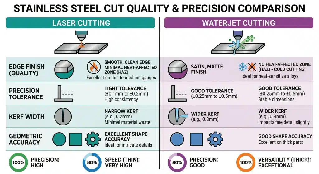
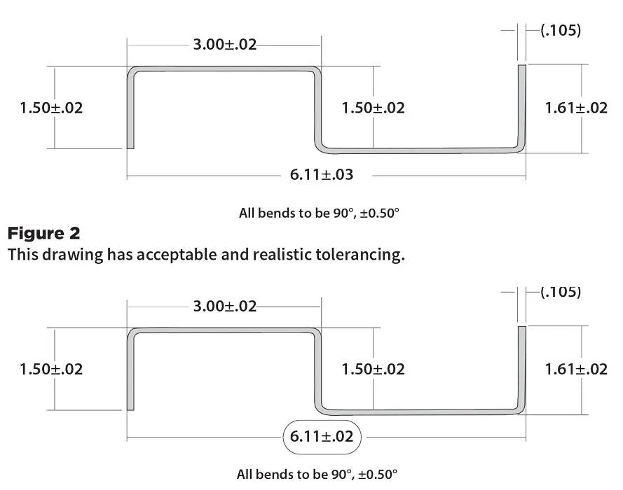
Calling ±0.1 mm on a laser-cut edge that normally holds ±0.2 mm forces secondary machining or 100 % inspection. Calling the same tolerance across a formed dimension that includes springback forces shimming or multiple setups.
Most functional fits do not need the tightest available tolerance. Apply tight numbers only where assembly or performance actually requires them. Everywhere else, use the process capability.
Over-tolerancing is one of the most expensive sheet metal fabrication mistakes because it is invisible until the first inspection report. The part may be fully functional at ±0.25 mm, yet the drawing forces the shop into precision processes that triple the cost of that feature.
Welding Design That Creates Access or Distortion Problems
Welds placed in tight corners, on both sides of thin walls, or in locations that require special fixtures increase labor hours. Continuous welds where intermittent would suffice add heat and distortion. Distortion then requires straightening or machining.
Design for weld access first. Prefer joints that can be reached with standard torch angles. Specify intermittent welds where strength allows. Keep heat input away from precision surfaces.
A common pattern is designing a box with internal welds that can only be made by a robot with a custom torch or by flipping the part multiple times. Each extra handling step adds cost and risk of dimensional drift. Simple changes to joint location or weld type often eliminate the problem entirely.
Processing Sequence That Forces Extra Setups
Bending before punching a critical hole, or welding before forming a flange, often creates interference or requires secondary fixturing. The correct sequence is usually cut → form → weld → finish. Deviating from that order without a clear reason adds handling and risk.
Review the process flow early. If a feature can only be made after forming, confirm the formed geometry still allows tool access. A hole that looks fine in the flat pattern can become unreachable once the flange is bent, forcing a secondary drilling or laser operation on a formed part.
Sequence mistakes are particularly costly because they are discovered late. The flat pattern is already nested and cut before anyone realizes the bend will trap a feature that needed to be punched earlier.
Surface Treatment Decisions Made Too Late
Leaving powder coat, plating, or passivation out of the original design forces last-minute process changes. Masking requirements, racking holes, or thickness allowances appear only after the parts are already cut. Cost and schedule both move.
Define the finish at the concept stage. Account for coating thickness on mating surfaces. Provide drain or vent holes where needed for plating or powder. A 50–80 µm powder layer can turn a slip fit into an interference fit if the designer never allowed for it.
Late surface-treatment decisions also create quality problems. Parts that were designed without racking points end up with finish defects or require expensive custom fixtures. The cost is not just the coating itself but the rework and the lost schedule.
Missing or Inadequate Bend Relief
Flanges bent without relief at the free ends crack or tear. The shop either scraps the part or grinds the tear and reworks the edge. Both cost money.
Relief width at least equal to thickness and depth equal to radius plus thickness prevents most of these failures. It is a zero-cost geometry change that removes a recurring scrap source. On harder materials the relief often needs to be larger—1.5× thickness in width is common practice.
The absence of relief is rarely intentional. It usually comes from treating the bend as a pure solid-model fold without considering how the free edge will behave under real forming forces. Once the tear appears, the only options are rework or scrap.
Holes and Features Too Close to Bends or Edges
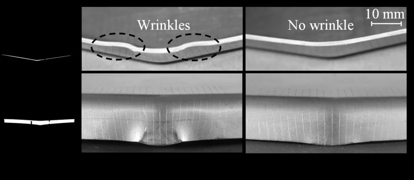
A hole whose edge sits inside the bend radius deforms during forming. The hole becomes oval or the surrounding material buckles. Edge distance smaller than 1.5–2× thickness often produces distortion or fracture.
Keep critical holes outside the bend zone. Maintain minimum edge distance. If a feature must sit near a bend, accept that it may need secondary sizing after forming. That secondary operation is almost always more expensive than moving the hole a few millimeters in the original layout.
This mistake is especially common when designers prioritize packaging density over formability. The CAD model shows clearance, but the forming process does not preserve that clearance once the material stretches and compresses.
Ignoring Standard Tooling and Sheet Thicknesses
Specifying a non-standard thickness or a bend angle that requires a custom die forces special material orders or special tooling. Both add cost and extend lead time.
Design around common gauges and standard punch/die sets whenever possible. The functional difference is often negligible. The cost difference is not. A 1.5 mm sheet is almost always available; a 1.7 mm sheet may require a mill minimum or long lead time.
The same applies to bend angles. Most shops stock common V-dies for 90° and a limited set of acute angles. Anything outside that set either requires a special die or a free-form air-bend that is harder to control. Both options increase cost.
How These Mistakes Compound Cost
Each of the issues above can be minor in isolation. Combined they multiply. A part with tight tolerances, missing relief, non-standard thickness, and late surface-treatment requirements can easily double the expected fabrication cost.
The pattern is consistent: design decisions made without process constraints create secondary operations, scrap, special tooling, and inspection burden. Those costs appear only after the model is released.
Catching the ten sheet metal fabrication mistakes listed here during layout review is the lowest-cost place to fix them. Once the parts are cut, the leverage is gone. The shop can only work with the geometry it is given, and every constraint the designer ignored becomes an extra process step the customer pays for.