In production we control laser cutting quality by locking the combination of power, speed, focus position, and assist gas to the material and thickness before the first sheet is loaded. The target is a clean, consistent edge with predictable kerf width, minimal heat-affected zone, and little or no dross. That parameter set, verified on a first-article check, is the practical foundation of laser cutting quality control sheet metal work on every job that runs through the shop.

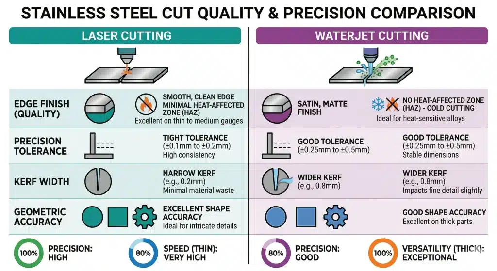
Quality is judged by a short list of measurable indicators. Dimensional accuracy must stay inside the process capability for the machine and material, typically ±0.1 mm or better on well-maintained fiber lasers for common thicknesses. Kerf width must be consistent so that internal features and external contours fit together without secondary adjustment. Edge roughness and perpendicularity affect both appearance and downstream operations such as welding or powder coating. The heat-affected zone must remain narrow enough that it does not change material properties or cause distortion. Burr or dross on the bottom edge must be low enough that it does not interfere with nesting, forming, or assembly. These indicators are checked together; improving one at the expense of another is not considered acceptable quality. On critical parts we also verify that the cut edge remains free of micro-cracks and that the top-edge rounding stays within the allowed limit for the subsequent process.
Why Thickness and Material Force Different Parameter Windows
Material thickness is the strongest driver of process change. Thin sheet (under 2 mm) cuts fast with modest power and produces a narrow kerf and small HAZ when focus and gas are correct. As thickness increases, power must rise and speed must fall to maintain full penetration. The kerf widens slightly, the heat-affected zone grows, and the risk of dross on the bottom edge increases. Mild steel, stainless, and aluminum each respond differently to the same settings because of differences in thermal conductivity, reflectivity, and melting behavior. Aluminum’s high reflectivity and thermal conductivity demand higher power density and often nitrogen assist to keep the edge clean. Stainless holds heat in a tighter zone and can produce a finer edge but is more sensitive to focus drift. Mild steel is more forgiving yet still shows clear quality drop-off when speed or gas pressure is outside the window.
Kerf width itself is not a fixed number. On thin mild steel it may stay under 0.2 mm; on 6–8 mm plate it can open to 0.3–0.5 mm depending on nozzle size and focus. The CAM system must apply the correct kerf compensation so that finished dimensions land on target. When the actual kerf drifts because of worn optics or incorrect focus, every internal opening and external contour shifts. That single variation is enough to cause fit-up problems at assembly or force secondary machining that was never quoted.
If these variables are left uncontrolled the defects appear quickly. Inconsistent kerf width causes parts that are either too tight or too loose in assembly. Excessive HAZ softens the edge or creates a hardened band that later cracks in forming. Heavy dross requires secondary grinding or deburring, adding labor and risking dimensional change. Rough or angled edges show up under powder coat or in welded joints. On thicker plate the combination of high heat input and slow speed can warp the sheet so that subsequent nesting or forming operations fail. Scrap, rework, and delayed shipments follow directly from parameter drift or from using a library setting that does not match the actual material batch.

How the Shop Actually Locks and Holds Cutting Quality
Process control starts with a verified parameter library organized by material grade and thickness. For each combination the shop records power, speed, focus offset, nozzle type and distance, and assist gas type and pressure. Nitrogen is preferred for stainless and aluminum when a clean, oxide-free edge is required; oxygen is used on mild steel when higher speed and a slight oxide edge are acceptable. Focus is set so the beam waist sits at the correct depth for the thickness—slightly into the material for thin sheet, closer to the surface or mid-thickness for thicker plate. Nozzle standoff is held constant because even small changes alter gas dynamics and edge quality. Gas pressure is balanced against speed so that the molten material is ejected cleanly without excessive turbulence that roughens the wall.
Before a production run the operator cuts a first-article coupon or the actual part and checks the critical indicators. Kerf width is measured with a pin gauge or optical system at several locations. Edge quality is inspected visually under good light and, when required, with a roughness comparator or low-power microscope. Bottom dross is evaluated by touch and by whether it breaks off cleanly or requires mechanical removal. Dimensional checks confirm that the programmed compensation for kerf is correct and that feature-to-feature distances remain inside tolerance. Perpendicularity of the cut wall is verified on thicker sections because an angled edge can shift the effective dimension after forming. If any indicator is outside the acceptance band the parameters are adjusted—usually speed or focus first, then gas pressure—and the check is repeated. Once the edge is acceptable the same settings are locked for the batch.
Periodic in-process checks on later parts catch focus drift, nozzle wear, or gas pressure changes before they produce scrap. On long runs the operator may pull a sample every few sheets or after a nozzle change. The acceptance criteria remain the same as the first article so that quality does not gradually degrade across the batch. When the material batch changes—new heat of stainless or a different aluminum temper—the first-article check is repeated even if the nominal thickness is the same. Small differences in chemistry or surface condition can shift the optimal speed or focus. The goal is to keep every sheet inside the same quality band rather than assuming the previous settings will transfer without verification.

Machine condition is treated as part of quality control. Lens and protective window cleanliness, nozzle condition, and beam alignment are checked on a schedule. Contaminated optics reduce power density and immediately degrade edge quality. Worn nozzles create uneven gas flow and increase dross. Beam alignment drift produces a tapered kerf or one-sided roughness. These maintenance items are not optional; they are required to keep the parameter library valid. For critical parts the shop may also record actual power output and gas flow during the run so that any deviation can be traced back to a machine or consumable issue rather than operator error.
When Tighter or Looser Control Is Accepted
Exceptions are limited. Cosmetic covers that will be fully painted may accept a slightly wider HAZ or minor dross that will be hidden by the coating. Structural or precision parts that feed into welding or tight assembly keep the full control regime. Prototypes sometimes run with temporary parameters for speed, but the production recommendation always returns to the verified library settings. When a customer specifies an unusually tight edge requirement or a maximum HAZ depth the shop confirms capability first and, if necessary, quotes additional inspection, slower cutting speed, or a change to nitrogen assist. In all cases the cost and schedule impact of the tighter window is made visible before the job is released.
Laser cutting quality is not left to chance or to a single "standard" setting. It is held by matching parameters to material and thickness, verifying the edge on the first article, monitoring the process during the run, and maintaining the machine so those parameters remain valid. That approach keeps dimensional accuracy, kerf consistency, HAZ size, and burr levels inside the limits the downstream processes expect and prevents the majority of cutting-related scrap and rework.