In a fabrication shop, the decision between prototype and production sheet metal fabrication is never about which process is "better." It is about matching the process to volume, design stability, and cost tolerance. Prototype methods keep the design flexible and the first parts on the table in days. Production methods lock the process, amortize tooling, and deliver consistent parts at lower unit cost once the design stops changing. Most shops see projects fail when a prototype process is forced into volume or when production tooling is ordered before the design is frozen.
Where Prototype Methods Still Win and Where Production Takes Over
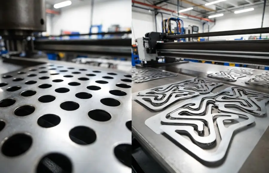
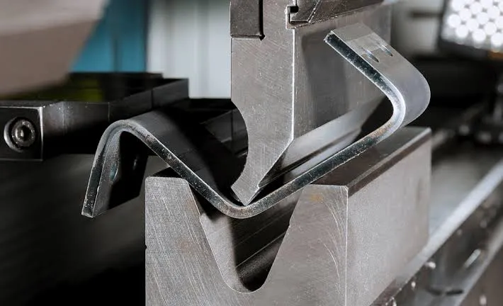
Prototype sheet metal fabrication is the practical choice when the design is still moving, quantities sit below a few hundred pieces, and the schedule cannot wait for hard tooling. Laser cutting, turret punching, and press-brake forming deliver parts without dedicated dies. Production sheet metal fabrication becomes the better route once the design is stable, annual volume exceeds a few thousand pieces, and unit cost or consistency starts to matter more than flexibility. At that point progressive dies, hard tooling, and dedicated fixtures pay for themselves through lower labor, higher throughput, and tighter process control.
The crossover is rarely a clean number. It depends on material thickness, part complexity, bend count, and how many design revisions are still expected. From a fabrication standpoint, the transition usually becomes obvious during the second or third design iteration when the same laser-cut and brake-formed parts keep returning with small changes.
Key Differences at a Glance
| Factor | Prototype Fabrication | Production Fabrication |
|---|---|---|
| Unit cost at low volume | Higher but acceptable | High due to tooling amortization |
| Unit cost at high volume | Remains high | Significantly lower |
| Tooling investment | Minimal or none | Substantial (dies, fixtures) |
| Lead time for first parts | Days to 2 weeks | 4–12 weeks for tooling + first article |
| Design change flexibility | High – change CAD and cut | Low – die modifications cost time and money |
| Dimensional consistency | Good, operator-dependent | Excellent, process-controlled |
| Typical volume sweet spot | 1–500 pieces | 2,000+ pieces per year |
| Material utilization | Nesting on sheet stock | Coil-fed progressive dies maximize yield |
Decision Matrix for Choosing the Right Path
| If your priority is… | Better Choice | Why |
|---|---|---|
| Fastest first parts | Prototype | No tooling lead time; laser and brake can start same day |
| Lowest unit cost at volume | Production | Tooling cost is spread across thousands of parts |
| Multiple design revisions expected | Prototype | CAD changes translate directly to new nests and brake programs |
| Tight, repeatable tolerances over long runs | Production | Hard tooling and fixtures remove operator variation |
| Bridge production of a few hundred pieces | Prototype or soft tooling | Avoids full progressive die cost while improving consistency |
| High-volume stamping with secondary operations minimized | Production | Progressive dies combine forming, piercing, and blanking in one stroke |
How Tooling Investment Changes the Economics
The single largest difference in prototype vs production sheet metal fabrication is tooling. Prototype work relies on standard tooling: laser or turret for blanking, standard V-dies and punch sets for bending, and off-the-shelf fixtures. The only "tooling" cost is programming time and perhaps a few soft jaws or simple templates. That keeps the first-article cost low and the barrier to design change almost zero.
Production work, especially progressive-die stamping, requires dedicated tooling. A progressive die for a moderately complex part can cost anywhere from several thousand to tens of thousands of dollars depending on material thickness, number of stations, and required die life. That cost is recovered only when the same die runs thousands of parts. Soft tooling (urethane forming, temporary fixtures, or modular dies) sits in the middle and is sometimes used for intermediate volumes, but it still carries higher setup cost and shorter life than hard tooling.
From a shop-floor perspective, ordering hard tooling before the design is frozen is one of the most expensive mistakes we see. A single design change after die steel is cut often means welding, grinding, or completely re-machining stations. Prototype methods absorb those changes with almost no penalty; production methods do not.
Lead Time Reality on the Shop Floor
Prototype lead times are driven by machine availability and material on hand. A straightforward laser-cut and brake-formed part can move from released CAD to finished parts in a few days if the material is in stock and the queue is light. Even with secondary operations such as hardware insertion or powder coating, two weeks is common.
Production lead times are dominated by tooling. Die design, material procurement for the die, CNC machining or wire EDM of the stations, try-out, and first-article approval routinely take four to twelve weeks. Once the die is approved, production runs themselves are fast—often measured in hours or days for thousands of parts. The long front-end is the reason most shops refuse to quote production tooling until the design is under formal revision control.
When a customer needs both speed and eventual volume, the practical path is prototype first, freeze the design, then cut production tooling. Running the early production builds on the prototype process while the die is being built is a common and effective bridge strategy.
Process Selection and Manufacturing Complexity
Prototype fabrication almost always starts with flat-pattern cutting—laser or turret—followed by press-brake forming. Complex forms may require multiple brake setups or hand-forming. Welding, hardware insertion, and finishing are secondary operations performed as discrete steps. The process is flexible but labor-intensive; every bend is programmed and checked, and every piece can be different if the design changes.
Production fabrication shifts the work into the die. A progressive die can blank, pierce, form, coin, and even extrude features in successive stations. The part exits the press essentially complete. Secondary operations are minimized or eliminated. The trade-off is that the process is rigid: once the die is built, adding a hole or changing a bend angle requires die modification. For very high volumes, coil-fed progressive dies deliver the lowest cost and highest consistency. For medium volumes, compound dies or stage tooling on a press brake with dedicated fixtures can be a reasonable compromise.
Nesting efficiency also diverges. Prototype nests are optimized for the current sheet size and the number of pieces needed that day. Production nests, especially on coil, are optimized for continuous running and maximum material utilization over the life of the job. Scrap rates drop noticeably once the process moves to progressive tooling.
Material Choices and Thickness Limits
Both prototype and production can run the common sheet metals—cold-rolled steel, stainless, aluminum, galvanized. The difference appears in thickness range, grain direction control, and coil versus sheet stock.
Prototype work is limited mainly by the laser or turret capacity and the brake tonnage. Most shops comfortably handle 0.5 mm to 6 mm or thicker with appropriate equipment. Material is purchased as sheets, so grain direction can be oriented for each nest if the part is sensitive to bending direction.
Production progressive dies prefer coil stock. Coil availability and width become constraints. Very thick materials (above roughly 4–5 mm depending on the press) start to push the limits of progressive tooling and may force a return to stage tooling or hydraulic presses. Springback compensation is also more carefully engineered into production dies because the process must hold tolerance without constant operator adjustment.
When material cost is a large fraction of the part cost, production methods win because nesting on coil and continuous running reduce scrap. For low volumes or exotic alloys that are only available in sheet form, prototype methods remain more practical.

Quality Requirements and Process Control
Prototype quality is typically verified by first-article inspection and occasional sample checks. Tolerances are achievable, but they depend on operator skill, machine calibration, and how carefully the brake programs are set. Variation from piece to piece is acceptable for most prototype and low-volume uses.
Production quality is controlled by the tooling and by process capability studies. Once a progressive die is proven, dimensional variation is largely a function of material thickness variation and press tonnage consistency. Statistical process control, in-die sensors, and automated inspection become practical and expected. Surface finish, burr height, and hole-to-bend relationships are more consistent because the same stations perform the same operations on every stroke.
Inspection requirements also escalate. Prototype jobs often accept a first-article report and a few dimensional checks. Production jobs commonly require capability data (Cp/Cpk), ongoing SPC charts, and tighter cosmetic standards because the parts are going into final assemblies that must fit and function without adjustment.
Design Iteration and the Cost of Change
This is the dimension that most clearly separates the two approaches. In prototype fabrication, a design change is a CAD update, a new nest, and a revised brake program. The shop can usually turn the change in days. The cost is mainly the material and machine time for the new pieces.
In production, a design change after the die is cut is expensive and slow. Even a small hole relocation can require inserting a new punch station or modifying an existing one. Bend angle or form changes often mean re-machining form blocks or adding coining stations. Many shops will quote a change order that includes both engineering time and machine time, and the schedule impact can be weeks.
Experienced customers therefore keep the design in prototype mode until form, fit, and function are proven in the actual application. Only then is the design frozen and production tooling released. Skipping this step is a common source of cost overruns and schedule slips.
How Fabrication Shops Evaluate the Two Paths
During DFM review we look first at expected volume and design maturity. If the drawing is still marked "prototype" or the customer cannot commit to a yearly quantity, we quote laser and brake. If the customer provides a firm annual volume and a controlled revision level, we evaluate progressive or stage tooling.
Nesting efficiency, press capacity, and material form (sheet versus coil) are checked next. Parts that nest poorly on sheet but would run well on coil are strong candidates for production tooling. Parts with many secondary operations that could be incorporated into a progressive die also move toward production.
Process risk is evaluated carefully. Prototype processes have low risk of total failure but higher risk of dimensional drift. Production processes have higher up-front risk (tooling that does not perform as expected) but much lower ongoing risk once the process is proven. We normally recommend a soft-tooling or prototype bridge build when the volume is uncertain or the design is still being validated in the field.
Panel utilization and machine loading also matter. A high-volume progressive job that keeps a press running for days is preferred over many small laser nests that consume programming and setup time. Conversely, a shop with excess laser capacity and limited press time will push customers toward prototype methods even at moderate volumes.
Which Path Should You Choose?
Choose prototype sheet metal fabrication if you:
- Need first parts in days rather than weeks
- Expect further design changes before freezing the geometry
- Are ordering fewer than a few hundred pieces in the near term
- Want to validate form, fit, and function in the real assembly before committing to tooling
- Are working with materials or thicknesses that are only practical in sheet form
Choose production sheet metal fabrication if you:
- Have a stable design under formal revision control
- Can forecast annual volumes in the thousands or higher
- Need the lowest possible unit cost and highest dimensional consistency
- Want to minimize secondary operations by incorporating features into the die
- Are willing to accept longer lead time and higher up-front tooling cost in exchange for long-term savings
For volumes that sit between a few hundred and a few thousand pieces, many shops recommend a hybrid approach: prototype or soft tooling for the first builds while hard tooling is designed and proven. This keeps the project moving without locking the design too early.
Frequently Asked Questions
Q1: At what volume does production tooling usually become cheaper than prototype methods?
A1: There is no fixed number, but for moderately complex parts the crossover often appears between 2,000 and 5,000 pieces per year once tooling cost is amortized. Simple flat parts with few bends may never justify progressive tooling; complex multi-form parts reach the crossover sooner.
Q2: Can I start with prototype and later convert the same design to progressive dies?
A2: Yes, and that is the recommended path. Keep the design in prototype until form and function are proven, then freeze the revision and release production tooling. Expect some minor process adjustments because laser edges and brake radii differ slightly from die-formed features.
Q3: How much does a typical progressive die cost compared with prototype setup?
A3: Prototype setup is usually a few hundred dollars in programming and fixtures. A progressive die for a medium-complexity part commonly ranges from several thousand to twenty thousand dollars or more, depending on material thickness, number of stations, and required production life.
Q4: What is the practical lead-time difference for the first 100 parts?
A4: Prototype can deliver 100 parts in days to two weeks. Production requires the tooling lead time first (often 6–10 weeks) before any production parts are available. Once the die is approved, 100 parts can be produced in a single shift.
Q5: Are there quality differences that affect assembly even if both methods meet the drawing tolerances?
A5: Yes. Production parts from hard tooling typically show less piece-to-piece variation in bend angles, hole positions, and flatness. That consistency reduces assembly time and the need for selective fitting. Prototype parts can meet the same tolerances on average but may require more adjustment at the assembly stage.
Q6: Is soft tooling a realistic middle ground for small-batch production?
A6: Soft tooling (urethane pads, modular dies, or temporary fixtures) can improve consistency and reduce labor compared with pure prototype methods while avoiding the full cost of progressive dies. It is useful for volumes of a few hundred to a few thousand pieces when the design is relatively stable but full hard tooling is not yet justified.