In most sheet metal shops, the decision between bending and welding is rarely about which process is "better" in absolute terms. It is about which process delivers the required strength, dimensional control, and cost at the volume you actually need. For chassis, brackets, and enclosures under 3 mm mild steel or aluminum, bending is usually the faster, cheaper, and more consistent route. Welding becomes necessary when geometry cannot be formed from a single piece, when closed-box strength is mandatory, or when material thickness exceeds what press brakes can reliably form without cracking.
From a fabrication standpoint, we default to bending first and only introduce welding when the design forces it. That single principle keeps scrap rates low and lead times short.
Where Each Process Fits in Real Production
| Factor | Bending | Welding |
|---|---|---|
| Typical cost (prototype to mid volume) | Lower – one setup, no filler, minimal post-process | Higher – joint preparation, consumables, grinding, distortion correction |
| Structural continuity | Grain flow remains continuous; good for static loads | Heat-affected zone creates local weakness; better for multi-directional loads when designed correctly |
| Dimensional precision | ±0.1–0.2 mm typical on modern CNC brakes | ±0.3–0.8 mm after distortion; requires fixtures or secondary machining |
| Surface appearance | Clean bend line, no discoloration if formed cold | Weld bead, spatter, heat tint; usually needs grinding and finishing |
| Production speed | High – seconds per bend once programmed | Lower – minutes per joint plus cooling and inspection |
| Tooling & setup | Standard punches and dies; quick change | Fixtures, clamps, sometimes custom jigs |
| Best thickness range | 0.5–6 mm (material dependent) | 1.5 mm and thicker; practical limit is higher |
| Typical applications | Chassis covers, L-brackets, open frames, simple enclosures | Closed boxes, multi-plane frames, heavy load-bearing brackets |

Quick Decision Matrix for Shop Floor Priorities
| If your priority is… | Better Choice | Why |
|---|---|---|
| Lowest unit cost at 50–500 pcs | Bending | No filler metal, no grinding time, higher panel yield |
| Closed-box rigidity or multi-directional strength | Welding | Bending alone cannot create continuous seams in three axes |
| Tight cosmetic appearance with minimal finishing | Bending | No heat tint or weld beads to hide |
| Fast prototype turnaround | Bending | Program and form in hours; welding needs fixtures |
| Material thicker than 4–5 mm with tight radii | Welding | Bending risk of cracking or large spring-back |
| High-volume repeatability with low operator skill | Bending | CNC brake programs are more stable than manual welding |
How the Processes Actually Differ on the Floor
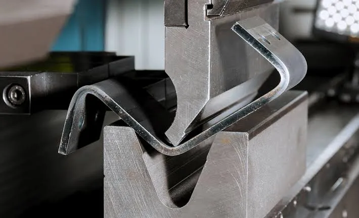
Bending is a cold-forming operation. The blank is positioned against a back-gauge, the punch descends, and the material yields around the die radius. Once the program is proven, cycle time is measured in seconds. Welding is a thermal joining process. Parts must be cleaned, fixtured, and tacked before the final weld. Heat input changes dimensions; the part almost always needs a secondary straighten or grind step. From a CAM and nesting standpoint, a bent part is usually nested as a single flat blank. A welded assembly is nested as multiple separate pieces that later consume welding capacity and inspection time.
The difference becomes obvious during first-article inspection. A bent chassis that was designed with proper bend relief and correct K-factor will measure within tolerance on the first try. A welded version of the same geometry often requires iterative fixture adjustment before it sits flat.
Structural Strength Trade-offs That Matter in Service
A properly calculated bend retains the original grain structure and work-hardens slightly at the outside radius. For static or low-cycle loads in the plane of the sheet, this is often stronger than a fillet weld of the same thickness. However, the bend has almost no strength against forces that try to open it. Welding can create a continuous load path in any direction, but the heat-affected zone is softer than the parent metal and becomes a preferential site for fatigue initiation if the design does not account for it.
In practice, we see bent brackets survive years of vibration when the load is compressive or shear along the bend line. The same bracket fails early if the customer later applies a peeling load. Welded structures handle multi-axis loading better, provided the welder maintains proper penetration and the designer avoids placing the weld in a high-stress concentration.

Where Cost Really Diverges
Material cost is almost identical for both routes if the finished geometry is the same. The divergence appears in labor and secondary operations. A bent part leaves the press brake ready for powder coating or plating. A welded part usually requires grinding of the weld bead, removal of spatter, and often a straightening step. At low volumes the difference can be 30–60 % higher for welding. At high volumes the gap narrows if robotic welding is used, but tooling and programming cost for the robot must still be amortized.
Panel utilization is another hidden factor. Nested bent blanks waste less sheet than the multiple smaller pieces required for welding. Most shops see 5–12 % better material yield on pure bending jobs.
Appearance and Finishing Reality
Customers who specify "no visible weld marks" are effectively specifying bending wherever possible. Even a well-executed TIG weld leaves a bead that must be ground flush and then polished if the surface is cosmetic. Heat tint on stainless or aluminum is another finishing cost that bending never incurs. For painted or powder-coated parts the difference is smaller, but grinding still adds time and risk of undercutting the parent metal.
Bending does leave a slight radius mark on the outside and a possible tool mark on the inside. These are usually acceptable or easily masked by texture coats. From a finishing department perspective, pure bent parts move through the line faster and with fewer rejects.
Precision and Repeatability on the Shop Floor
Modern CNC press brakes with angle compensation and laser measurement deliver bend angles within ±0.5° and linear dimensions within ±0.15 mm on most materials under 3 mm. Welding, even with fixtures, fights thermal distortion. A 400 mm long chassis can grow or shrink 0.5–1.5 mm depending on weld sequence and heat input. Shops that must hold tight tolerances on welded assemblies often add a secondary machining or straightening operation, which again raises cost and lead time.
For chassis and mounting brackets that must fit existing holes or rails, bending is the more predictable process. When the design requires a fully sealed box, welding is unavoidable and the designer must allow for post-weld adjustment or accept looser tolerances.

Production Efficiency and Lead-Time Impact
Once the program is proven, a press brake can run unattended for short runs with an automatic tool changer. Welding almost always requires an operator at the station. Throughput for bending is therefore higher, and scheduling is simpler. In a typical job shop, a pure bending job of 200 chassis covers can ship in 3–5 days after material arrives. The same geometry made as welded assemblies often takes 8–12 days because of fixture design, welding capacity, and finishing queue time.
Batch size also changes the equation. Below roughly 30–50 pieces, the setup cost of welding fixtures is hard to justify unless the geometry simply cannot be bent. Above a few hundred pieces, robotic welding starts to close the efficiency gap, but only if the product life is long enough to amortize the robot program and fixtures.
Assembly and Downstream Considerations
Bent parts arrive at the assembly station as single pieces. Welded assemblies arrive already joined, which can reduce assembly labor if the weld replaces fasteners. The trade-off is that any dimensional error in the welded assembly propagates into the next stage. Bent parts can be adjusted slightly during assembly with a soft hammer or clamp; a welded box cannot.
For electronic chassis that must accept PCBs, fans, and connectors, the higher dimensional stability of bending usually reduces rework at the assembly line. For structural frames that carry heavy loads or must be sealed against dust and water, welding is often the only practical route.
How Fabrication Shops Evaluate the Choice During DFM
During CAM review we look first at whether the part can be unfolded into a single blank without excessive scrap or impossible bend sequences. If the answer is yes and the thickness is within the brake's comfortable range, we push hard for bending. We check bend radii against material minimums, confirm that bend reliefs are present, and verify that the final dimensions can be held after spring-back compensation.
If the geometry forces multiple pieces, we then decide between welding and mechanical fastening. Welding is chosen when continuous strength or sealing is required; otherwise we prefer rivets or clinching to avoid heat distortion. We also evaluate panel utilization, expected weld length, and whether the welds will be in high-stress locations. Process risk is higher with welding because operator skill and heat management affect yield more than a programmed brake cycle.
Most shops will recommend redesigning a borderline part so that critical dimensions are achieved by bending and only non-critical seams are welded. That hybrid approach often gives the best combination of cost, strength, and lead time.
Which Method Should You Choose for Chassis and Brackets?
Choose bending if you:
- Need open or partially open chassis, covers, or simple L- and U-brackets
- Are working with 0.8–3 mm mild steel, stainless, or aluminum
- Prioritize cosmetic appearance and minimal secondary finishing
- Require tight dimensional control for PCB mounting or rail fits
- Are producing prototype to mid-volume quantities where speed matters
- Want the lowest possible piece price without sacrificing basic structural integrity
Choose welding if you:
- Must create a fully closed box or multi-plane frame that cannot be formed from one blank
- Need continuous load paths in more than one plane or high peel resistance
- Are using material thicker than about 4–5 mm where bending risk rises sharply
- Require sealed joints against dust, water, or EMI without gaskets
- Are producing structural frames that carry significant static or dynamic loads
- Can accept the extra cost and lead time in exchange for design freedom
In many real chassis designs the optimal solution is hybrid: the main body is bent as a single piece and only the end caps or internal reinforcements are welded. That approach keeps most of the cost and speed advantages of bending while still delivering the closed geometry or extra stiffness where it is needed.
Frequently Asked Questions
Q1: Is a bent joint always weaker than a welded joint of the same thickness?
A1: No. For loads that stay in the plane of the sheet or that compress the bend, a properly formed bend is often stronger because the grain remains continuous. Welding introduces a heat-affected zone that is softer. The welded joint only becomes superior when the load tries to peel the joint open or when multi-directional strength is required.
Q2: How much more expensive is welding compared with bending for a typical chassis?
A2: In the 50–300 piece range the welded version commonly costs 30–60 % more once grinding, straightening, and extra handling are included. At very high volumes with robotic welding the gap can shrink to 15–25 %, but fixture amortization must still be considered.
Q3: Can I get the same dimensional accuracy from welding as from CNC bending?
A3: Not without extra operations. CNC bending routinely holds ±0.15 mm. Welded assemblies typically hold ±0.5 mm or worse unless they are post-machined or carefully straightened. Designers who need tight hole-to-hole or overall dimensions almost always prefer bending.
Q4: When does thickness make bending impractical?
A4: For mild steel, most shops start to discourage tight-radius bends above 4–5 mm because of cracking risk and large spring-back. Stainless and high-strength steels reach the practical limit earlier. At that point welding or a combination of bending plus welding becomes the safer production route.
Q5: Is there a hybrid approach that shops commonly recommend?
A5: Yes. Form the main body and critical mounting features by bending, then weld only the features that cannot be formed—end plates, internal ribs, or sealed corners. This keeps most of the process in the high-speed, high-yield bending department while still delivering the closed or reinforced geometry the design needs.
Q6: Does material type change the bending-versus-welding decision?
A6: Mild steel is the most forgiving for both processes. Aluminum is easier to bend than to weld cleanly at production speed; heat distortion is more pronounced. Stainless requires careful heat control when welded and often shows more spring-back when bent. In all three materials the same geometry-driven logic applies: bend when you can, weld when you must.