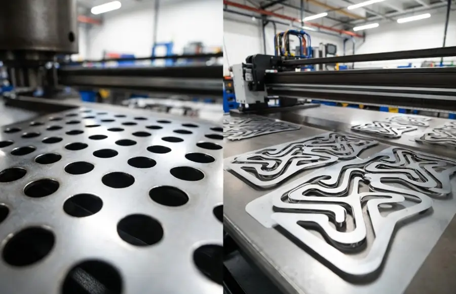
In production we run the sheet metal fabrication process as a fixed sequence: CAD data review and nesting, material preparation, laser cutting or punching, forming/bending, welding or joining, surface treatment, assembly if required, and final inspection. CAM engineers load the flat pattern, apply kerf compensation and grain direction rules, then release the job only after confirming that bend radii, hole-to-edge distances and weld access all stay inside machine capability. Most shops keep the entire flow under one work order so that any dimensional shift found at inspection can be traced straight back to the station that caused it.

Where machine capability and material behavior force the process limits
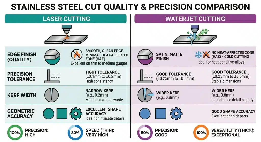
Sheet metal does not stay flat and uniform once it leaves the coil. Thickness variation of ±0.05 mm on 1.5 mm cold-rolled steel is common; laser power density and assist-gas pressure change the kerf width by 0.05–0.1 mm depending on focus position; press-brake springback varies with grain direction and tensile strength. These are not design preferences—they are physical limits of the equipment and the material. When a designer places a hole closer than 1.5× thickness to a bend line, the punch or laser will either deform the hole during forming or leave insufficient material for the die to support. The same constraint appears at welding: a gap larger than 0.5 mm on thin gauge forces the operator to add filler and risk distortion. Production therefore builds compensation tables into the CAM software and into the press-brake angle programs so that the finished part still meets the drawing after every process has moved the metal.
What shows up on the floor when those limits are ignored
Uncontrolled kerf leaves parts undersize; the next station then tries to bend a blank that is already short and the bend angle opens further. Springback that is not compensated produces flanges that sit 1–2° out of square; downstream welding fixtures cannot clamp them, so the welder hammers the joint and introduces residual stress. Coating thickness on a part that was over-bent will be uneven because the powder or paint cannot reach the tight inside radius. In assembly the mis-matched holes force reaming or slotting, which delays the line and creates scrap. Shops that skip intermediate checks routinely see 8–12 % scrap on the first production batch of a new design, plus overtime for rework and delayed shipments while the customer waits for replacement parts.

How the line actually keeps every station inside tolerance
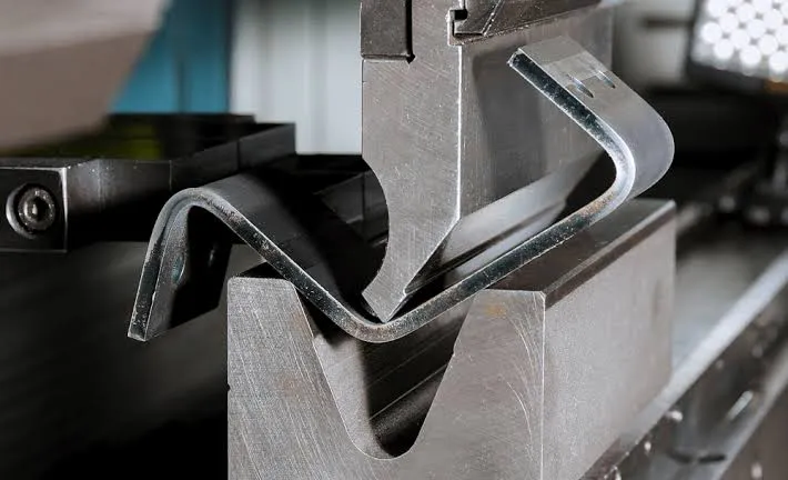
CAM starts with a flat-pattern check: minimum bend radius is set to 1× thickness for mild steel and 1.5× for stainless; hole-to-bend distance is forced above 2× thickness; laser lead-in and micro-joint positions are placed so the part does not fall into the scrap skeleton. Material is then staged with grain direction marked; coils or sheets are cut to exact blank size only after the nesting program has locked the orientation. Laser or turret punch runs with real-time kerf measurement on the first article; the offset is written into the program for the remainder of the batch. At the press brake the operator measures the first bend with a digital protractor, adjusts the punch depth or V-die opening according to the springback table, and only then runs the full quantity. Welding fixtures are built with 0.3 mm intentional gap and water-cooled clamps for thin gauge; MIG or TIG parameters are locked to a WPS that limits heat input. Surface treatment follows a written sequence—degrease, phosphate or conversion coat, then powder or plating—with thickness checked by magnetic gauge at three points per part. Final inspection uses first-article CMM or optical scan against the 3D model; critical dimensions receive 100 % check, the rest sample to AQL 1.0. Every deviation is logged against the station that produced it so the next batch inherits the corrected program.
When the strict sequence can be relaxed
Prototype quantities under ten pieces sometimes skip full nesting and run on a job-shop laser with manual grain orientation; the customer accepts a wider tolerance band and longer lead time. Soft aluminum or very thin gauge (≤0.8 mm) may allow tighter bend radii than the standard tables because the material yields more easily, but only after a first-article bend test confirms the result. Cosmetic-only parts can accept larger weld gaps if the joint is later covered by a cover plate or powder coat. These exceptions are written into the traveler and signed by both the process engineer and the customer; they never become the default for production volumes. Once the batch size exceeds fifty pieces or the part goes into a regulated assembly, the full control sequence is reinstated without debate.