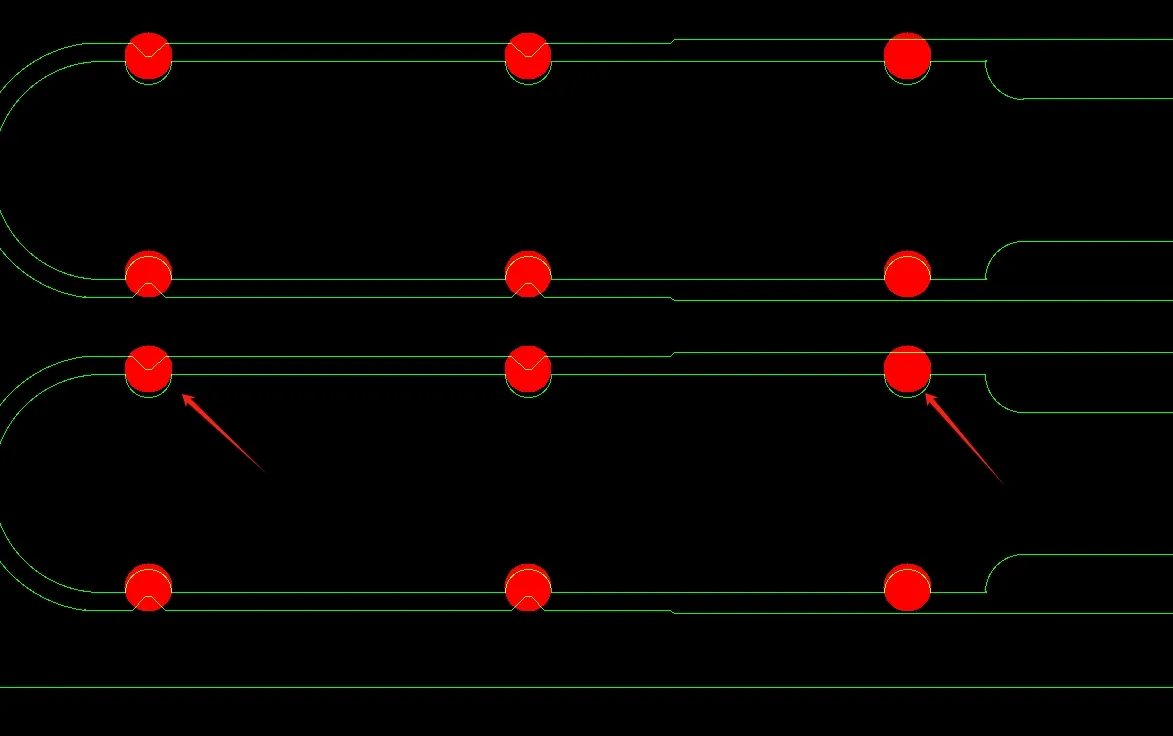
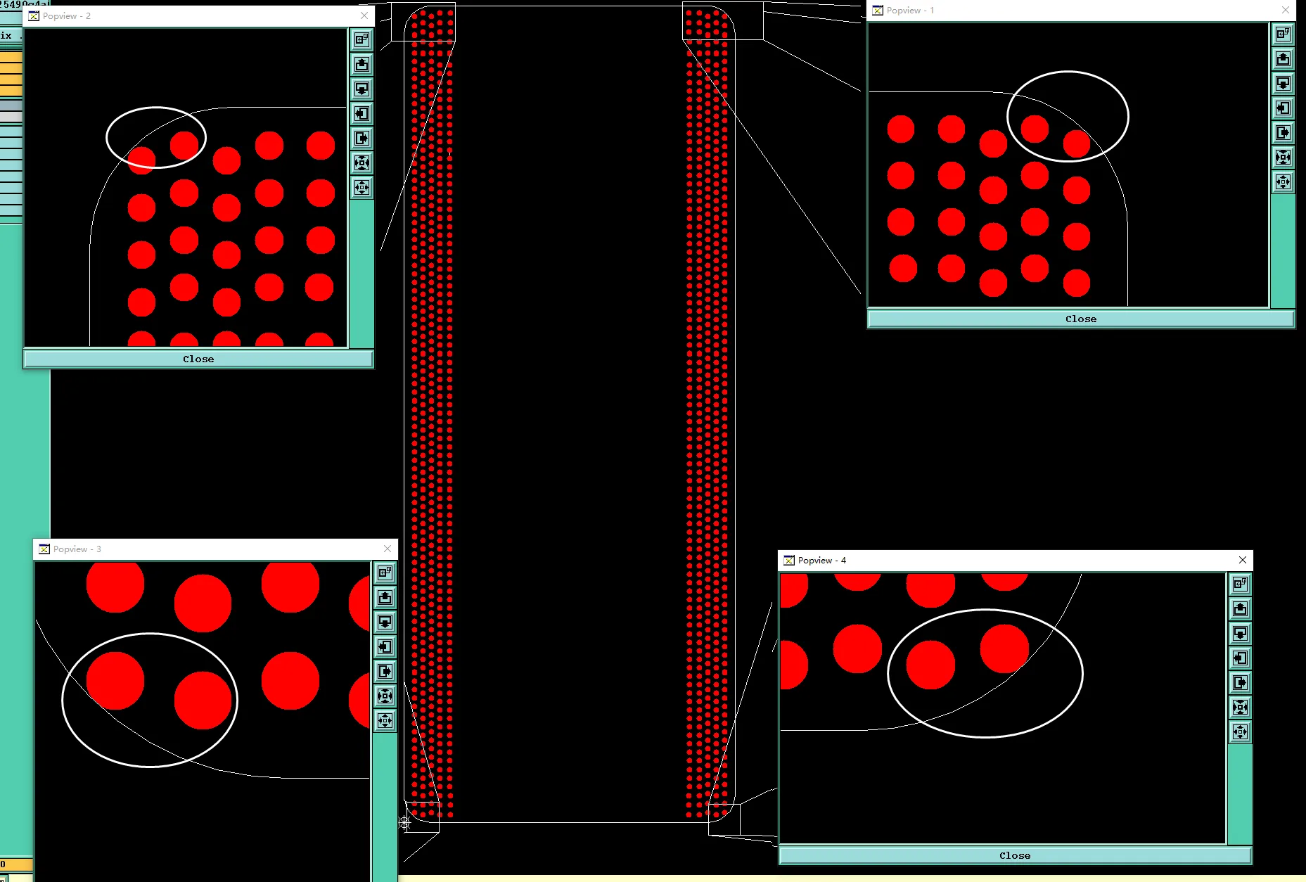
A production data package containing multiple Gerber sets arrived for CAM review with no single file clearly designated as the authoritative source. The submission included several versions of the board geometry, each carrying its own mechanical layers labeled GM1 and GM3, along with separate drill data that did not align with the slots shown on one of the outline layers. During verification the team could not determine which layer defined the finished board contour or which geometry governed the internal slots. Without that clarification the routing path, contour tolerance, and final outline dimensions remained open to conflicting interpretations. The investigation therefore centered on establishing a single, manufacturable definition of the PCB outline layer before any tooling could be released.
Apparent Design Intent Across Multiple Gerber Sets
The customer had supplied more than one complete set of production files. Each set contained its own mechanical layers, and the naming convention used GM1 and GM3 to identify outline-related data. One file appeared to represent an earlier design iteration while another carried later revisions. The presence of multiple files suggested that the designer intended the factory to select the most recent or most complete version, yet no explicit instruction identified which package should govern manufacturing. Internal slots drawn on the drill layer differed in length and position from the corresponding features on the GM1 layer. The overall intent appeared to be a board ( #FR4-20260306-083 ) whose external contour and internal cut-outs would be formed by mechanical routing, but the data itself left the controlling geometry undefined.
In the absence of a clear hierarchy among the submitted files, any automatic selection risked producing a contour that the customer did not expect. The CAM review therefore treated the multiplicity of files as the first indicator that design intent could not be read with certainty.
Multiple Files and Competing Outline Definitions
The initial data audit revealed three overlapping sources of outline geometry. One mechanical layer labeled GM3 carried a complete external contour. Another layer labeled GM1 showed a similar but not identical outline together with internal slots. The drill file contained slot coordinates that matched neither layer exactly. In addition, the package contained an earlier set of Gerbers that the customer had not marked as obsolete. Our CAM engineer noted that the factory's standard practice is to treat a single, clearly identified mechanical layer as the contour authority; when several candidates exist, production cannot proceed without an explicit choice.
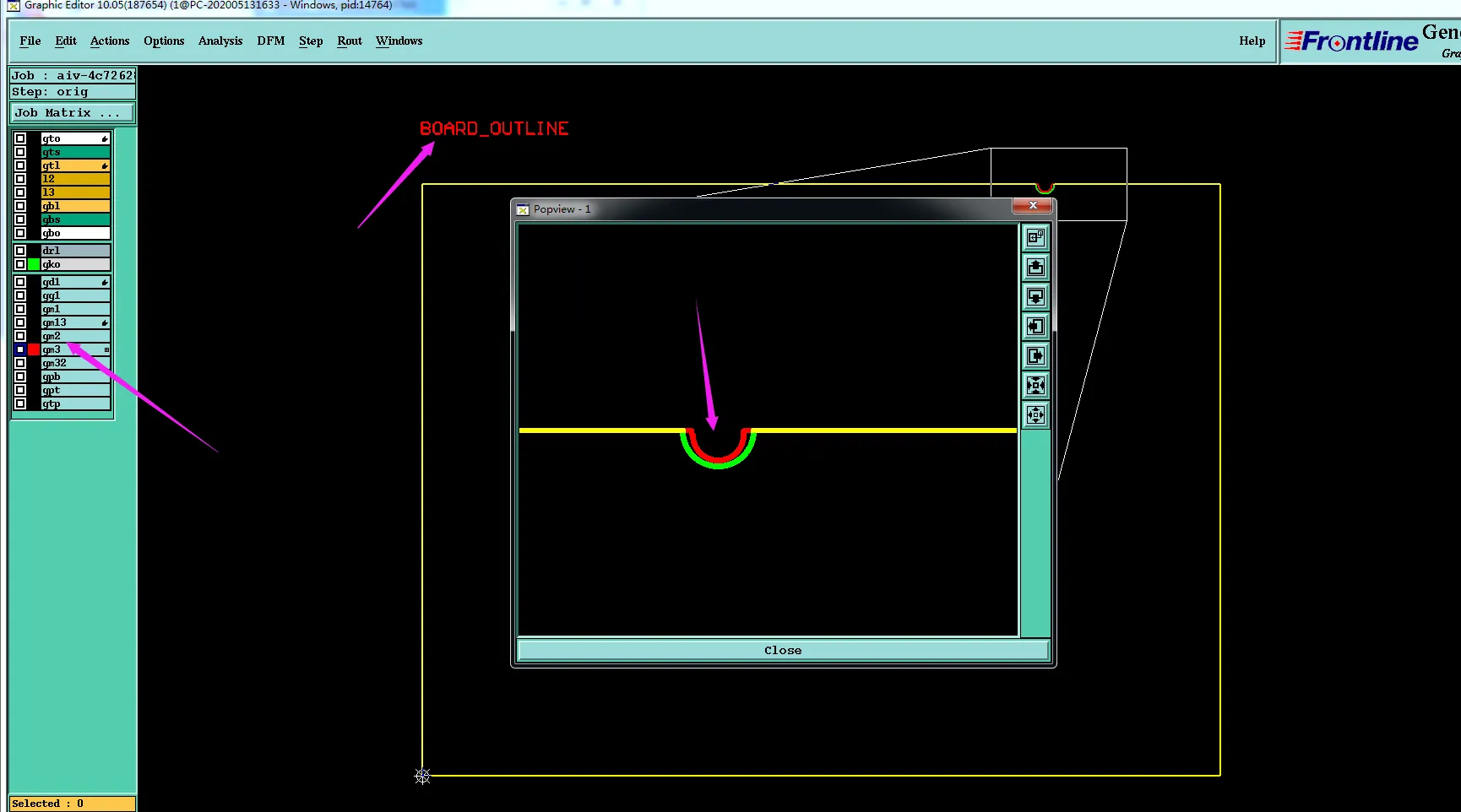
Figure 1: use GM3 to make outline
If the GM3 layer had been selected without confirmation, any slots present only on GM1 would have been omitted, potentially leaving uncut material inside the board. If the GM1 layer had been followed, the external dimensions might have differed from the customer's latest expectation. Selecting the wrong file set entirely would have reproduced an obsolete outline. Each of these outcomes would have produced a finished FR4 board whose contour failed to match the designer's intended geometry, creating dimensional non-conformance under typical IPC-A-600 Class 2 criteria and possible fit problems at assembly.
| Data Source | Outline Feature Present | Slot Geometry | Risk if Selected Alone |
|---|---|---|---|
| GM3 Mechanical Layer | Complete external contour | Limited or absent | Internal slots may be omitted |
| GM1 Mechanical Layer | Alternate external contour | Slots present | External dimensions may differ from expectation |
| Drill File | — | Slot coordinates differ from GM1 | Routed slots misaligned with intended cut-outs |
| Earlier Gerber Set | Obsolete contour | Unknown | Entire board manufactured to superseded design |
Primary Conflict: Undefined PCB Outline Layer Authority
The dominant conflict belonged to the combined categories of documentation conflict and manufacturing-interpretation conflict. Multiple Gerber packages existed without a stated hierarchy, and within the preferred package the GM1 and GM3 layers offered competing definitions of the board outline and internal slots. The drill file further diverged from the GM1 slot geometry. Because mechanical routing relies on a single, unambiguous contour path, the factory could not generate a reliable NC routing program until one layer was declared authoritative.
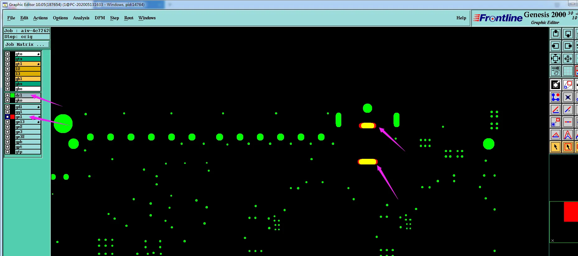
Figure 1: The slot indicated by the arrow are different on the drilling layer and the GM1 layer.
Design intent could not be determined with confidence for three reasons. First, the presence of several complete file sets left open the possibility that an earlier version was still being referenced by the customer. Second, the GM3 layer carried a clean external outline while the GM1 layer carried the slots; selecting either layer alone would have omitted critical geometry. Third, the drill-to-GM1 discrepancy on slot length and position meant that even within one file set the cut-out features were not self-consistent. Production release was therefore blocked: any unilateral choice would have constituted an uncontrolled interpretation of the customer's data.
If the conflict had been ignored, two realistic manufacturing outcomes were possible. Routing exclusively to the GM3 outline would have left internal material uncut where slots were required, potentially causing mechanical interference or thermal issues depending on the board's function. Routing to the GM1 outline while following the drill file for slots could have produced an external contour that no longer matched the customer's latest drawing, resulting in dimensional rejection or PCB assembly fit problems. In either case the finished boards would have failed to embody a single, coherent design intent.
Supporting Observations on Slot and File Consistency
Secondary findings reinforced the need for a single outline authority. The arrow-marked slots on the drill layer differed from those on GM1 in both coordinate position and finished length. On a board formed by mechanical routing, such a discrepancy directly affects the final cut-out size and location. In addition, the sheer number of submitted files increased the probability of an operator selecting an obsolete package during CAM import. These observations did not constitute independent primary conflicts, yet they confirmed that the data package as received could not be translated into a unique manufacturing path without customer direction.
Clarification Process and Authoritative Layer Selection
The engineering reply presented a clear set of decisions for customer confirmation. First, the factory proposed to treat one specific PCB file (the version indicated by the review arrows) as the sole production source and to ignore all earlier file sets. Second, the external contour would be taken exclusively from the GM3 layer. Third, the internal slots would follow the geometry shown on the drill layer where it conflicted with GM1, because the drill file is the conventional source for plated or non-plated openings. The reply explicitly stated that once these choices were accepted, the CAM data would be regenerated from that single file and the selected layers only.
Customer confirmation accepted the proposal in full. The production file was locked to the indicated PCB data set, the GM3 layer became the outline authority, and the drill-file slot coordinates were adopted for all internal cut-outs. All other Gerber packages were archived and excluded from the manufacturing database. The resulting CAM output contained one external contour path and one consistent set of slot coordinates. Tooling was released without further holds.
| Engineering Observation | Conflict Identified | Recommended Action | Final Status |
|---|---|---|---|
| Multiple complete Gerber sets submitted | No authoritative production file | Lock to the arrow-indicated PCB file; ignore originals | Confirmed |
| GM3 vs GM1 external contours differ | Competing outline definitions | Adopt GM3 as sole outline layer | Confirmed |
| Drill-layer slots diverge from GM1 | Internal cut-out inconsistency | Follow drill-file slot geometry | Confirmed |
Design Lessons for Clear Outline Layer Definition
- Submit only one complete, current set of Gerber files; archive or clearly mark obsolete packages so the factory cannot select them by accident.
- Designate a single mechanical layer as the board-outline authority and state that designation in a fabrication note.
- Ensure that internal slots appear consistently on both the drill file and the chosen outline layer; any discrepancy will trigger an Engineering Question.
- When multiple mechanical layers (GM1, GM3, etc.) exist, provide a short hierarchy note explaining which layer controls the external contour and which controls cut-outs.
- Avoid relying on file-name conventions alone; an explicit "use this file for production" statement removes ambiguity.
- Verify that the drill-file coordinates for slots match the graphical representation on the mechanical layer before release to the manufacturer.
- Remember that mechanical routing programs are generated from one contour path; competing outlines cannot be averaged or combined without customer direction.
FAQ
Q1: Why does the presence of multiple Gerber sets trigger an Engineering Question?
A1: Without a stated hierarchy the factory cannot know which package represents the current design intent. Selecting the wrong set would produce an obsolete or incorrect outline.
Q2: What is the risk of having both GM1 and GM3 layers define the board outline?
A2: The two layers may differ in external dimensions or internal features. Routing to one while the customer expects the other creates dimensional non-conformance.
Q3: Why are drill-file slot coordinates given priority over a mechanical-layer drawing?
A3: The drill file is the explicit tool list used to generate the NC program. When it conflicts with a graphical layer, the numerical coordinates are treated as the more precise source unless the customer directs otherwise.
Q4: Can the factory simply combine GM1 and GM3 features?
A4: No. Combining layers without authorization would create a hybrid geometry that neither file originally contained, violating the requirement to manufacture to the customer's defined data.
Q5: How should designers indicate the authoritative outline layer?
A5: Include a short fabrication note that names the specific mechanical layer (for example, "Board outline defined by GM3") and states that all other mechanical layers are for reference only.
Q6: What happens if slot geometry differs between the drill file and the outline layer?
A6: The factory cannot generate a single routing path that satisfies both sources. Confirmation is required to decide which coordinates will define the finished cut-outs.
```