










A 4-layer FR-4 board with 3 oz copper on both outer and inner layers, 1.6 mm finished thickness, and ENIG surface finish arrived for CAM review under factory number AIV-4E7496135. The design called for a 2x1 panel with 4 mm process edges and mechanical routing separation. Among the fabrication notes, one requirement stood out immediately: press-fit holes were specified, yet no finished hole size (FHS), drill size, plating thickness, or tolerance class accompanied the callout. The only related data available was a set of 1.45 mm original apertures that the engineering team would need to interpret and control. This single omission triggered a formal Engineering Question because press-fit hole performance depends on tightly controlled finished diameter, plating uniformity, and hole wall integrity—parameters that cannot be assumed when the customer provides no explicit values.
In parallel, several non-plated through-holes measured 12.5 mm in diameter. At that size, standard drilling becomes impractical; the holes must be routed, and the achievable tolerance window shifts from typical drilled-hole capability to routing capability. Both issues required a process-capability assessment before the order could be released to production.
PCB Press-Fit Hole Design Without Explicit Finished Hole Size
The PCB ( #H4B-Y12R-AI18364A ) fabrication data listed press-fit holes but supplied no accompanying table of finished hole sizes, drill oversize recommendations, or plating requirements. The only measurable feature that could be associated with the press-fit callout was a population of 1.45 mm original apertures. In the absence of customer-defined FHS, the process engineer must decide whether those 1.45 mm holes are intended as the finished size after plating or as the pre-plate drill size. The distinction is critical.
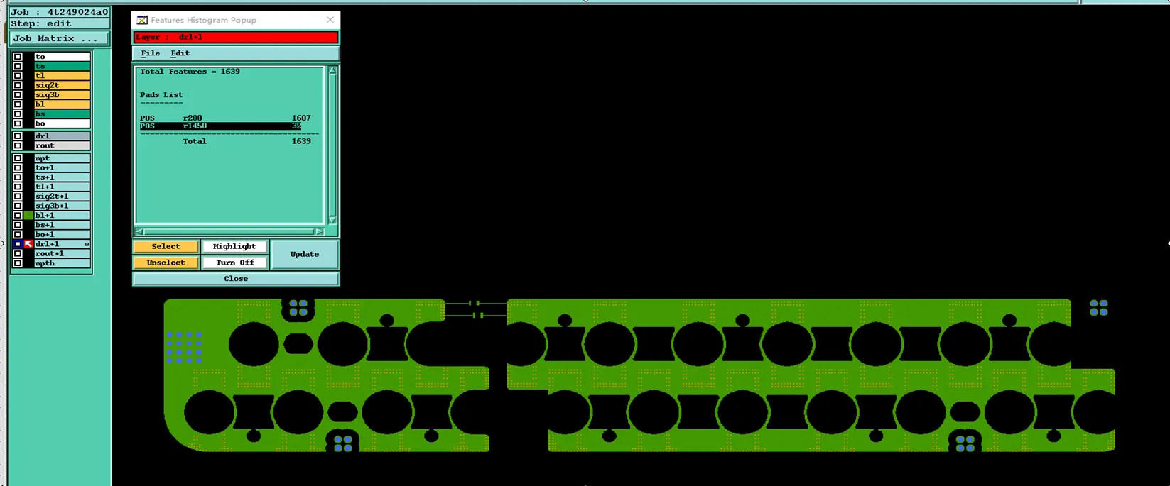
Figure 1: no countersink hole details
For compliant-pin (press-fit) connectors, the finished hole diameter must fall within a narrow window—typically ±0.05 mm or tighter around the nominal pin size—so that the compliant section of the pin achieves the correct interference fit. Too large a finished hole produces insufficient retention force; too small a hole risks excessive insertion force, pin deformation, or barrel damage. When the design supplies only a 1.45 mm dimension and labels the feature "press-fit," the manufacturing team cannot know whether the customer expects:
- 1.45 mm as the finished hole size after copper plating and surface finish, or
- 1.45 mm as the drill size, with plating still to be added.
Either interpretation changes the required drill diameter, the copper plating thickness target, and the final process window. Without clarification, production cannot proceed under controlled conditions.
Process Capability Window for Press-Fit Finished Hole Size
Standard plated through-hole capability on a 1.6 mm, 3 oz copper board typically holds finished hole diameter to ±0.075 mm after plating for holes in the 1.0–2.0 mm range. Press-fit applications frequently demand tighter control—often ±0.05 mm or better—because the mechanical reliability of the connection depends on consistent interference. The presence of 3 oz copper further narrows the practical process window. Heavier copper requires longer plating times or higher current densities, both of which increase the risk of non-uniform copper thickness along the hole wall. Any local variation in plating thickness directly translates into finished-hole-size variation.
| Parameter | Typical Capability (3 oz, 1.6 mm) | Press-Fit Expectation | Engineering Assessment |
|---|---|---|---|
| Finished hole tolerance | ±0.075 mm | ±0.05 mm or tighter | Requires confirmation of FHS and plating target |
| Copper plating thickness | 18–25 µm average | Uniform wall, controlled min/max | Heavy copper increases non-uniformity risk |
| Drill size selection | Based on known FHS + plating | Must match pin manufacturer recommendation | 1.45 mm alone is ambiguous |
The engineering decision was therefore to treat the 1.45 mm dimension as the controlled finished-hole target pending customer confirmation, while noting that the actual drill size would be adjusted once the required plating thickness and final FHS were clarified. This approach keeps the process within a measurable capability window rather than allowing uncontrolled plating variation to determine the final diameter.
Large-Diameter NPTH Routing and Tolerance Limits
A second set of features required capability evaluation: non-plated through-holes of 12.5 mm diameter. At this size, mechanical drilling with conventional PCB drills is neither accurate nor economical. The holes must be formed by routing. Routing introduces a different set of process variables—tool deflection, spindle run-out, and panel registration—that expand the achievable tolerance relative to drilled holes.
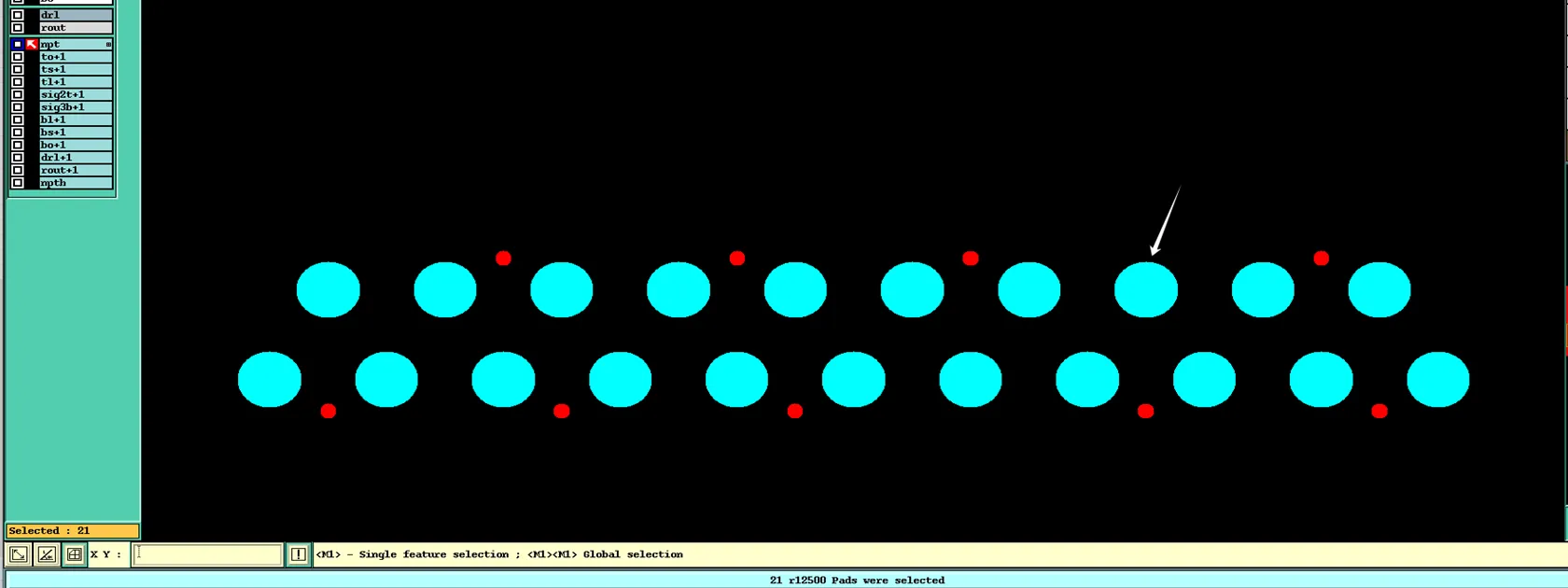
Figure 2: these 12.5mm non-plated holes are too large and can only be routed out
Industry practice for large routed openings typically holds diameter to ±0.13 mm under normal production conditions on 1.6 mm FR-4. Tighter tolerances are possible with specialized tooling and reduced feed rates, but they increase cycle time and reduce tool life. The EQ therefore proposed controlling the 12.5 mm NPTH features to ±0.13 mm and asked the customer to confirm acceptance. This recommendation rests on measured process capability rather than an arbitrary design preference.
| Feature | Requested Diameter | Forming Method | Recommended Tolerance | Rationale |
|---|---|---|---|---|
| Large NPTH | 12.5 mm | Routing | ±0.13 mm | Standard routing capability on 1.6 mm FR-4 |
| Press-fit PTH | 1.45 mm (ambiguous) | Drill + plate | Pending FHS confirmation | Plating uniformity critical |
Heavy Copper Interaction with Press-Fit Hole Plating
The board carries 3 oz copper on both outer and inner layers. Heavy copper increases the absolute volume of copper that must be deposited inside the press-fit holes if the finished diameter is to remain controlled. Longer plating times or higher current densities are required, both of which raise the probability of thickness variation from top to bottom of the hole and from hole to hole across the panel. On a 1.6 mm board the aspect ratio is modest, yet the combination of heavy copper and the need for tight finished-hole tolerance still compresses the process window.
According to common plating practice referenced in IPC-6012, minimum copper thickness in holes is typically specified as 20 µm or 25 µm for Class 2 or Class 3, respectively. The order listed an 18 µm hole copper thickness, which is already near the lower practical limit for reliable press-fit performance. Any further reduction caused by local plating depletion would move the finished hole diameter outside the interference range required by most compliant-pin connectors. The engineering team therefore flagged the need for explicit confirmation of both the target finished hole size and the minimum acceptable copper thickness before committing the panel to plating.
Surface Finish Considerations for Press-Fit Holes
The specified surface finish is immersion palladium-gold (ENEPIG). While ENEPIG provides excellent solderability and wire-bond capability, its interaction with press-fit pins must be evaluated. The palladium and gold layers add a small but measurable thickness to the finished hole wall. If the customer's pin manufacturer specifies a bare copper or electroless-nickel immersion-gold (ENIG) finished diameter, the additional palladium-gold stack can shift the interference fit. The process assessment therefore included a note that the final FHS after ENEPIG must still meet the mechanical requirements of the press-fit pin once the nominal size is confirmed.
Panelization and Secondary Process Controls
The panel was constructed as a 1×2 array with 4 mm process edges on all sides and 2 mm routing channels. Bridge-and-stamp-hole depaneling was proposed, with bridge locations identified for customer approval. These secondary features do not directly affect press-fit hole capability, yet they influence overall dimensional stability. Any residual stress from routing or stamp-hole punching can locally distort the board, which in turn can shift the measured finished hole diameter relative to the nominal grid. The engineering review therefore treated panelization as a supporting control that must remain consistent once the primary press-fit and large-NPTH dimensions are locked.
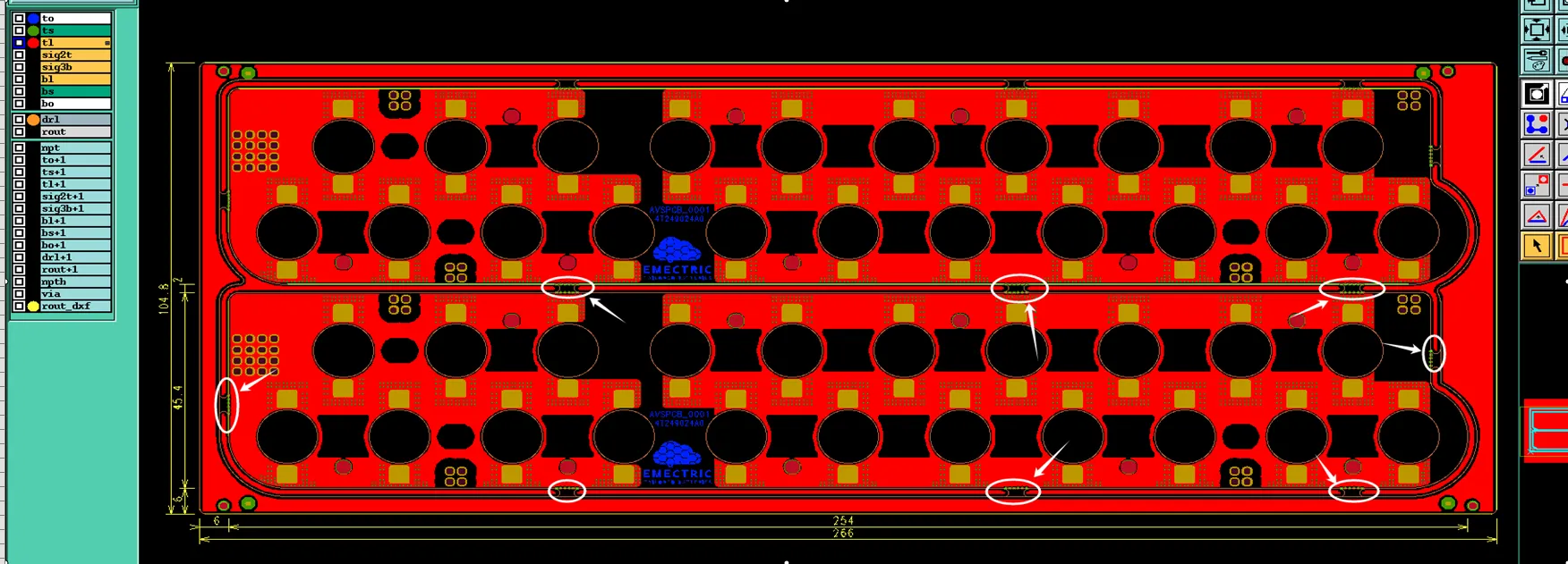
Figure 3: suggested panelization drawing
Two minor documentation issues—characters placed outside the board outline and overlapping silkscreen text—were also raised. Both were resolved by simple confirmation that the characters could be omitted or repositioned without affecting electrical or mechanical function. These items did not alter the process-capability evaluation of the press-fit or large-NPTH features.
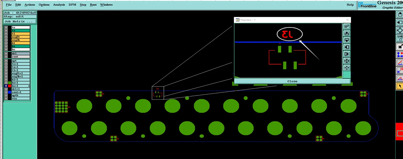
Figure 4: the J3 silkscreen is designed outside the board
Capability Assessment and Recommended Manufacturing Window
The core manufacturing decision rested on two controllable parameters:
- Finished hole size and plating thickness for the 1.45 mm press-fit features.
- Routed diameter tolerance for the 12.5 mm NPTH openings.
Until the customer confirmed the intended finished hole size for the press-fit holes and accepted the ±0.13 mm tolerance on the large routed holes, the process window remained undefined. Releasing the board under an assumed FHS would expose production to the risk of either insufficient retention force or excessive insertion force on the compliant pins. Likewise, attempting to hold the 12.5 mm openings to a drilled-hole tolerance would force an unrealistic process expectation.
| Process Element | Difficulty | Capability Margin | Stability | Action Required |
|---|---|---|---|---|
| Press-fit FHS control | High | Narrow until FHS confirmed | Dependent on plating uniformity | Customer confirmation of 1.45 mm intent |
| Large NPTH routing | Moderate | Adequate at ±0.13 mm | Stable under standard routing | Tolerance acceptance |
| 3 oz copper plating | Elevated | Reduced by heavy copper | Requires monitoring | Verify min wall thickness |
Once the customer confirmed that the 1.45 mm dimension represented the controlled finished hole size and accepted the proposed ±0.13 mm tolerance on the routed openings, the manufacturing process could be locked. Drill size was selected to leave sufficient copper after plating to meet the 18 µm minimum while still landing inside the press-fit interference window. Plating parameters were adjusted for the 3 oz outer copper to maintain wall uniformity. The large NPTH features were programmed for routing with the agreed tolerance. With these controls in place, the order proceeded under a defined and measurable process capability window.
Conclusion
The engineering review of this 4-layer, 3 oz copper board centered on the absence of explicit finished-hole-size data for the press-fit features and the practical tolerance limits of large-diameter routed NPTH openings. By treating the 1.45 mm apertures as the provisional finished-hole target and proposing a ±0.13 mm routing tolerance for the 12.5 mm holes, the process remained inside a controllable manufacturing window. Customer confirmation of both points allowed the plating and routing processes to be fixed, ensuring that the finished press-fit holes would deliver consistent mechanical performance and that the large openings would meet dimensional requirements under normal production conditions. The case illustrates how a missing specification, rather than an inherently unmanufacturable design, can force a capability evaluation before production release.
FAQ
Q1: Why does a PCB press-fit hole design require explicit finished hole size data?
A1: Compliant-pin connectors rely on a precise interference fit. The finished hole diameter after plating and surface finish must fall within a narrow window—often ±0.05 mm—around the pin manufacturer's recommended size. Without a stated finished hole size, the fabricator cannot select the correct drill diameter or control plating thickness, leaving retention force and insertion force uncontrolled.
Q2: How does heavy copper affect press-fit hole plating thickness control?
A2: Heavier copper requires longer plating times or higher current densities. Both increase the risk of thickness variation along the hole wall and from hole to hole. On a 3 oz board the process window for finished hole size is therefore narrower than on a standard 1 oz design, making explicit minimum copper thickness and finished-hole-size targets essential.
Q3: What tolerance is realistically achievable for large-diameter NPTH openings formed by routing?
A3: For openings in the 10–15 mm range on 1.6 mm FR-4, standard routing capability typically holds diameter to ±0.13 mm under normal production conditions. Tighter tolerances are possible with specialized tooling but increase cost and cycle time. Designers should specify a tolerance that matches the forming method rather than assuming drilled-hole capability.
Q4: Does ENEPIG surface finish change the finished hole size for press-fit applications?
A4: Yes. The palladium and gold layers add a small but measurable thickness to the hole wall. If the pin manufacturer's recommendation is based on bare copper or ENIG, the additional ENEPIG stack can shift the interference fit. The final finished hole size after ENEPIG must still meet the mechanical requirements of the specific press-fit pin.
Q5: Why is the distinction between drill size and finished hole size critical for press-fit holes?
A5: Drill size is the tool diameter used before plating. Finished hole size is the diameter after copper plating and surface finish. Press-fit performance is governed by the finished diameter. Specifying only a single dimension without clarifying whether it is drill or finished leaves the plating allowance undefined and the final interference uncontrolled.
Q6: How should designers document press-fit hole requirements to avoid capability questions?
A6: Provide a clear finished hole size (or a drill size plus plating allowance), the required copper thickness range, the surface-finish stack-up, and the applicable tolerance class. Reference the pin manufacturer's recommended hole size whenever possible. This information allows the fabricator to select tooling and process parameters that keep production inside a stable capability window.
```






