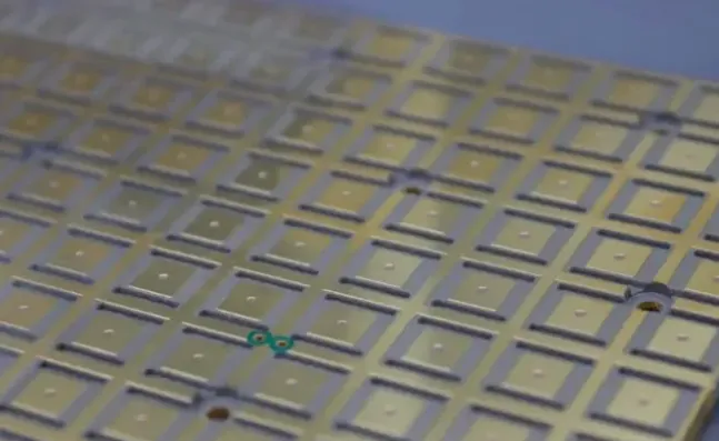
In production, 8-layer PCB reliability is controlled by locking the stackup early, enforcing copper balance across the panel, and setting via plating and aspect-ratio limits that the process can actually hold. CAM engineers pull the gerbers, measure residual copper on every layer, flag any via above 8:1–10:1 depending on the shop's plating capability, and add thieving or dummy copper where the outer or inner layers are unbalanced. The board is then run with a controlled lamination cycle and a minimum 20–25 µm hole-wall copper on critical vias. That combination is what keeps the usual failure modes—via barrel cracks, resin starvation, and post-reflow warp—inside the yield window.

Where the Lamination and Thermal Cycle Force the First Cracks
An 8-layer board sees two or three press cycles and a large z-axis expansion when it goes through assembly reflow or thermal cycling. Standard FR-4 has a CTE around 45–60 ppm/°C below Tg and jumps to 200+ ppm above Tg. The copper barrel of a via expands only about 17 ppm. That mismatch opens micro-cracks at the knee of the barrel, especially on the outer layers or at the interface of a buried via. Resin flow during the second and third press is also limited; if the prepreg is already partially cured or the copper density is too high in one area, you get resin-starved spots that later delaminate under heat. In the shop this shows up as voids in the microsection or as an electrical open after 500–1000 thermal cycles.
Warpage appears for the same reason. When one side of the panel has 70% residual copper and the opposite side has 20%, the board bows as it cools from the press. On an 8-layer the inner planes can lock that bow in place. The finished panel then sits outside the 0.75% or 1% bow-and-twist limit and cannot be assembled flat.

What the Board Actually Does When the Controls Are Missing
Without the copper-balance check, the panel warps 1.5–2% after lamination. Routing and electrical test still pass, but the boards arrive at assembly with enough bow that the stencil does not seat and the BGA joints open or bridge. Via failures show up later. A 12:1 aspect-ratio via plated to only 15 µm average copper cracks after a few hundred cycles; the open is intermittent and only appears after the product has been in the field for months. Delamination at the prepreg interface creates a moisture path; under bias and humidity the board develops conductive anodic filament or simply a leakage current that fails the insulation-resistance test. Scrap at electrical test rises, rework at assembly climbs, and the lot is delayed while the shop re-runs microsections and process audits.
How the Shop Actually Keeps the Board Inside the Process Window
On the CAM side we force residual copper into the 40–60% range on every layer by adding thieving pads or solid copper fills in the low-density areas. For an 8-layer the outer layers are balanced against each other and the inner planes are checked as a pair. The stackup is locked to a single material system—usually a mid-Tg or high-Tg FR-4 with matched prepreg—so the press recipe stays the same from prototype to volume. Via aspect ratio is capped at the shop's qualified limit (commonly 8:1 for standard plating, 10:1 with pulse plating or thicker copper). Hole-wall copper is specified at 20–25 µm minimum and verified by microsection on every lot; the plating bath is adjusted so the distribution stays inside ±5 µm.
Lamination uses a controlled ramp and a soak above Tg long enough for the resin to fill the gaps created by the copper features. Registration targets are measured after the first press and the drill program is offset if the shift exceeds 50 µm. For boards that will see more than 1000 thermal cycles we switch to a higher-Tg material (170 °C or above) and increase the via copper to 25–30 µm. Surface finish is chosen for the assembly profile: ENIG or immersion silver for fine-pitch, OSP only when the storage time is short and the reflow is mild. Solder mask is applied with a minimum 50 µm dam and is cured to a hardness that survives the reflow without cracking over the via pads.

Where the Factory Will Accept a Looser Limit
For low-volume prototypes or boards that stay below 85 °C and see fewer than 200 thermal cycles, the shop will often accept a 10:1 via and 18 µm copper if the microsection still shows continuous plating and no voids. Copper balance can be relaxed to 30–70% residual when the panel size is small and the assembly process can handle 1% bow. High-Tg material is skipped if the customer's thermal profile never crosses 150 °C and the cost difference is material. Those exceptions are written into the DFM reply so the designer knows the board is outside the standard reliability window and that any later field return will be reviewed against the agreed process limits.
Electrical test, thermal-cycling coupons, and routine microsections are the checks that confirm the controls worked. The same data set is what the factory uses to decide whether a design can stay on the standard process or must move to a tighter plating and material package.