


 00:53
Impedance Control
Impedance control is a critical aspect of printed circuit board (PCB) design, ensuring that signal traces maintain consistent electrical characteristics to prevent distortions, reflections, and data loss in high-speed applications. This tag encompasses a range of topics related to managing characteristic impedance in PCBs, from fundamental concepts to advanced implementation strategies. For engineers and designers searching for impedance control solutions, understanding this principle is essential for optimizing performance in systems like telecommunications, computing, and automotive electronics, where signal integrity directly impacts reliability and efficiency. At its core, impedance control involves precise calculation and control of trace geometry, dielectric materials, and layer stackups to match the required impedance values, typically 50 ohms for RF signals or 100 ohms for differential pairs. Practical applications include high-speed interfaces such as USB, PCIe, and Ethernet, where mismatches can lead to electromagnetic interference or signal degradation. Best practices start with accurate simulations using tools like field solvers to predict impedance, followed by selecting appropriate trace widths, spacing, and via configurations. For instance, maintaining uniform trace routing and incorporating ground planes can minimize variations, while regular testing with time-domain reflectometry ensures compliance during prototyping. Professionals often encounter challenges like manufacturing tolerances or environmental factors affecting impedance, which this tag addresses through case studies and troubleshooting guides. By delving into these resources, you can gain actionable insights to refine your designs, such as integrating controlled impedance into multilayer boards or adapting to flexible PCBs. Exploring the articles under this tag provides in-depth discussions on these techniques, helping you apply proven methods to your projects and achieve robust, high-performance electronics.
Video Guide

Technical Articles

PCB Design for UAV Flight Controllers, ESCs, and RF Links
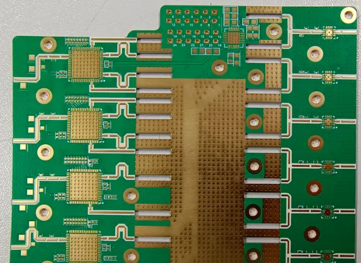
From Signal Frequency to Signal Integrity: What Is the Fundamental Difference Between High-Frequency and High-Speed PCBs?
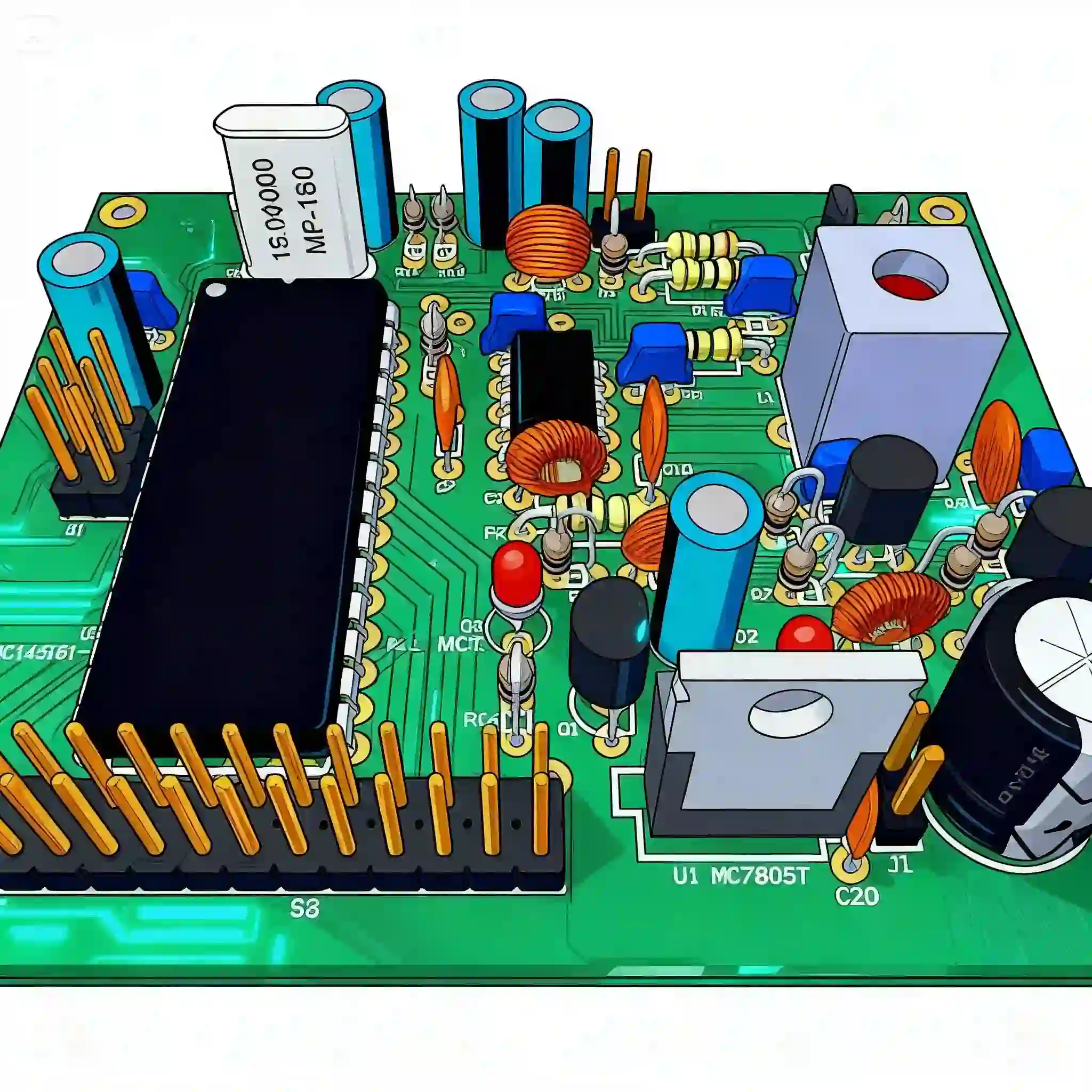
Enhancing USB PCB Performance: A Guide to Optimal PCB Layout and Signal Integrity
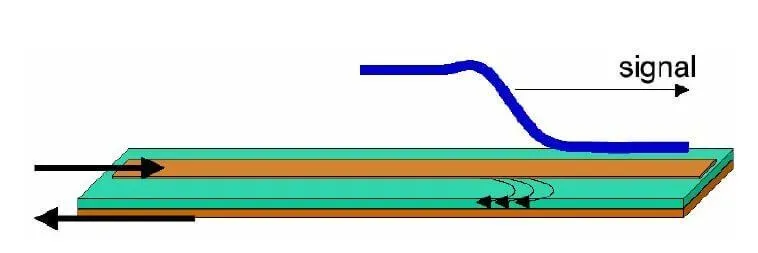
DIY PCB Impedance Measurement: A Home Lab Guide
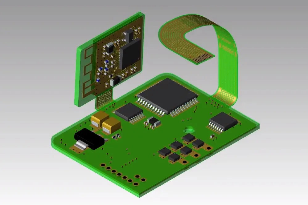
Rigid-Flex PCBs: The Ultimate Solution for Complex Wearable Health Monitors

4-Layer FPC CAM Review: Stackup and Mask Opening Design

How Does Stackup Design Differ Between Through-Hole and HDI PCBs?

What Do 7628, 2116, and 1080 Mean in PCB Materials?

4-Layer FPC Stackup Design and FR4 Stiffener Adjustments

2-Layer Flexible PCB Stackup and Impedance Design Optimization

Is the Nickel in Thick Gold Plating the Same as the Nickel in ENIG?

IPC-2221 Standard: PCB Design Rules and Requirements

4-Layer FPC CAM Review: Stackup Design and Impedance Control

CAM Review of a 4-Layer FPC: Fine-Line Manufacturing, PI Material Substitution, and Impedance Challenges

Essential Knowledge of High-Speed and High-Frequency PCBs

How to Manage Severe PCB Laminate Shortages

4-Layer FPC Stack-Up Optimization and Impedance Adjustment for Adhesiveless Construction

EMC Fundamentals: Disturbance and Interference Control Terms

EMC Measurement, Equipment Classification, and Transceiver Terms


