Mixed-Signal Grounding
Mixed-signal grounding refers to the specialized techniques used in printed circuit board (PCB) design to manage ground planes in systems that integrate both analog and digital components. This approach is essential for minimizing noise interference, ensuring signal integrity, and preventing issues like ground loops that can degrade performance in sensitive electronics. Engineers and designers often search for information on mixed-signal grounding when troubleshooting problems such as electromagnetic interference (EMI) or when optimizing layouts for applications like audio equipment, sensors, or communication devices. By separating analog and digital grounds while providing a common reference point, typically through a star grounding scheme or careful partitioning, you can achieve cleaner signals and more reliable operation. Understanding the principles of mixed-signal grounding empowers you to apply best practices in real-world scenarios. For instance, placing analog components away from high-speed digital traces and using ferrite beads or decoupling capacitors can significantly reduce crosstalk. In high-frequency designs, techniques like multi-layer PCBs with dedicated ground planes become crucial to isolate noise sources. These methods not only comply with standards such as those from the IPC but also enhance overall system efficiency, making them invaluable for hobbyists building prototypes or professionals developing commercial products. Common pitfalls, such as improper via placement or inadequate shielding, are addressed in depth to help you avoid costly revisions. The articles under the Mixed-Signal Grounding tag delve into these topics with detailed examples, case studies, and step-by-step guides. Whether you are refining a mixed-signal PCB layout or seeking solutions to persistent noise issues, these resources provide the technical depth needed to implement effective grounding strategies in your projects.
Technical Articles
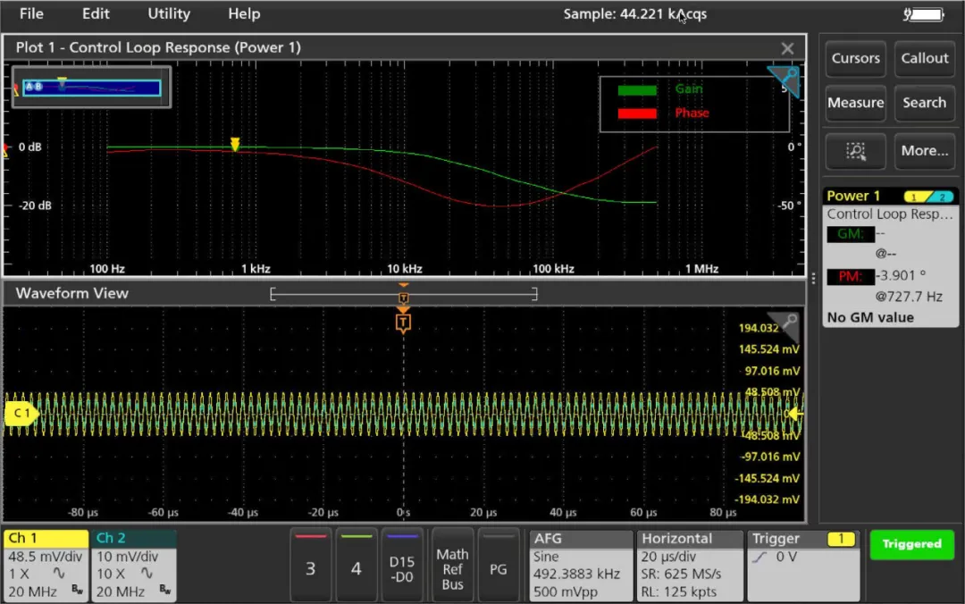
Frequency Response Analysis with an Oscilloscope
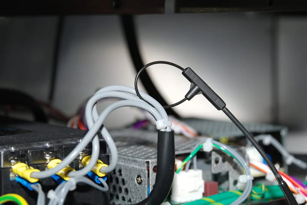
Types, Principles, and Use of Current Probes
Multimeter FAQs and Common Problems
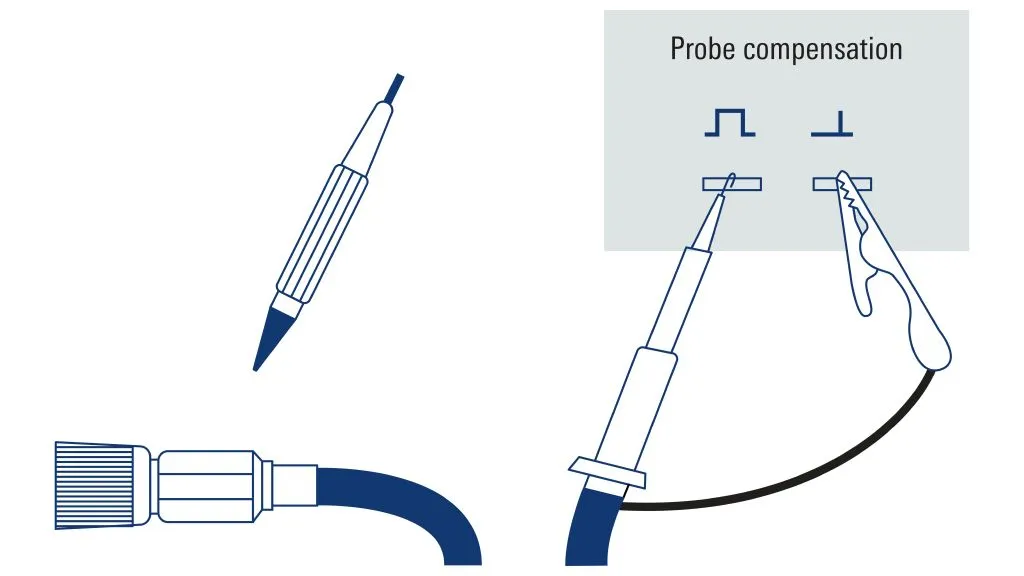
Differences Between Active and Passive Probes
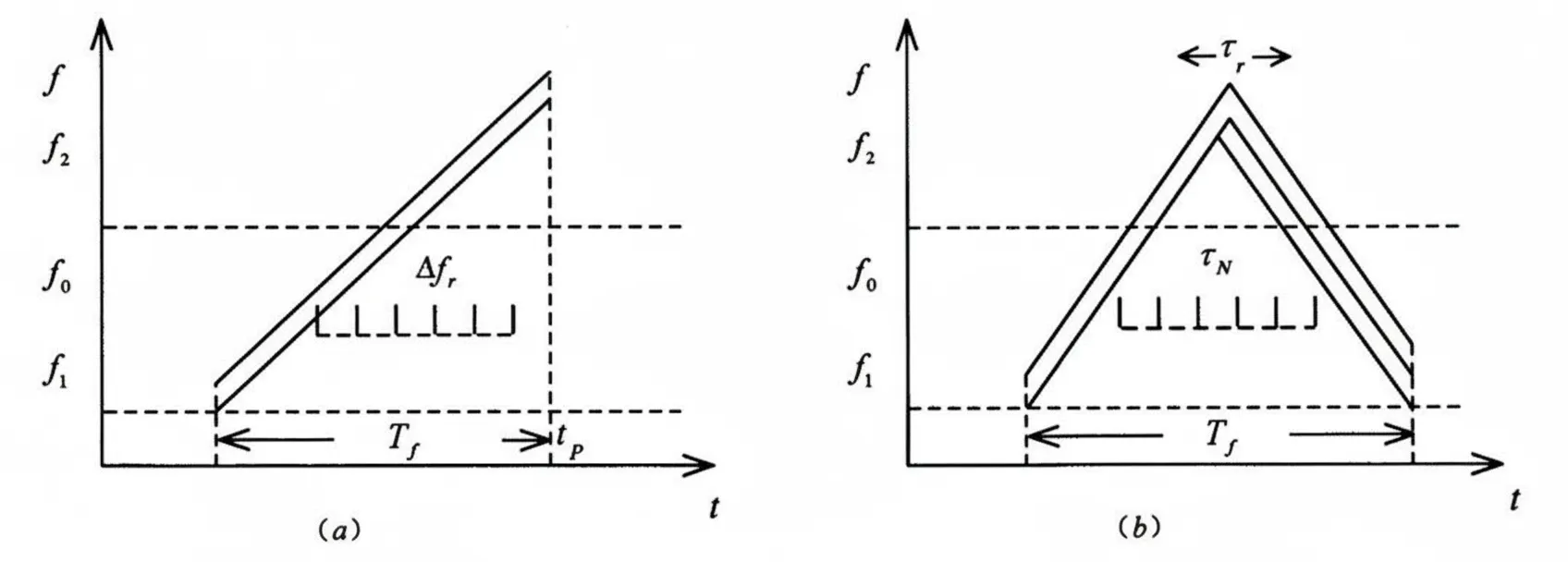
Search Superheterodyne Radar Frequency Measurement
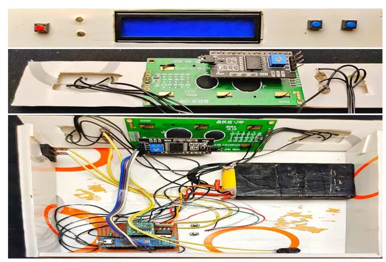
Building a Portable Load Scale with HX711, Arduino, and Load Cells: PCB Design Insights
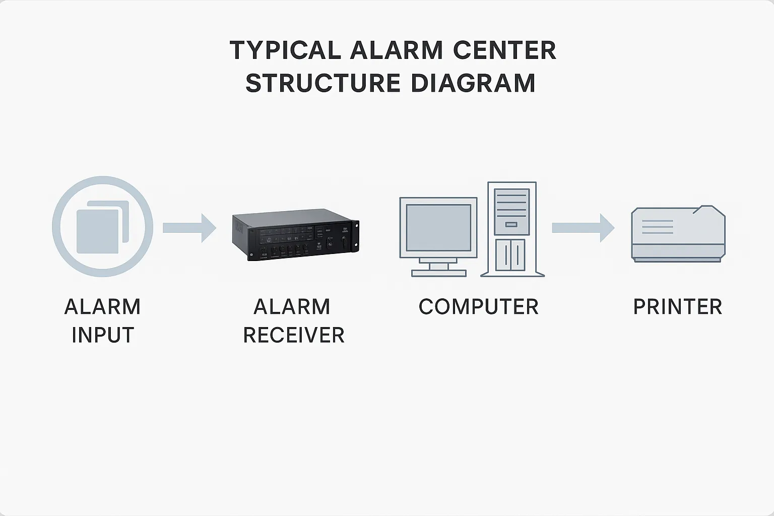
Intrusion Alarm System Design and Applications

White-Plus-Black Technique: Attack and Defense Analysis
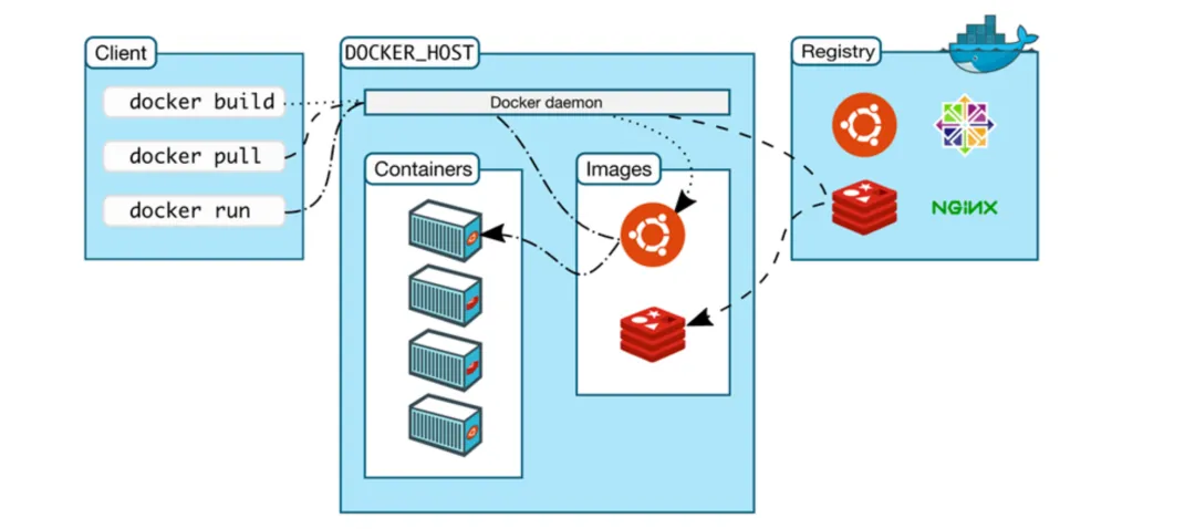
How Cloud Security Differs from Traditional Security

Capacitive vs Resistive Touchscreens: Principles, Comparison, and PCB Design Insights
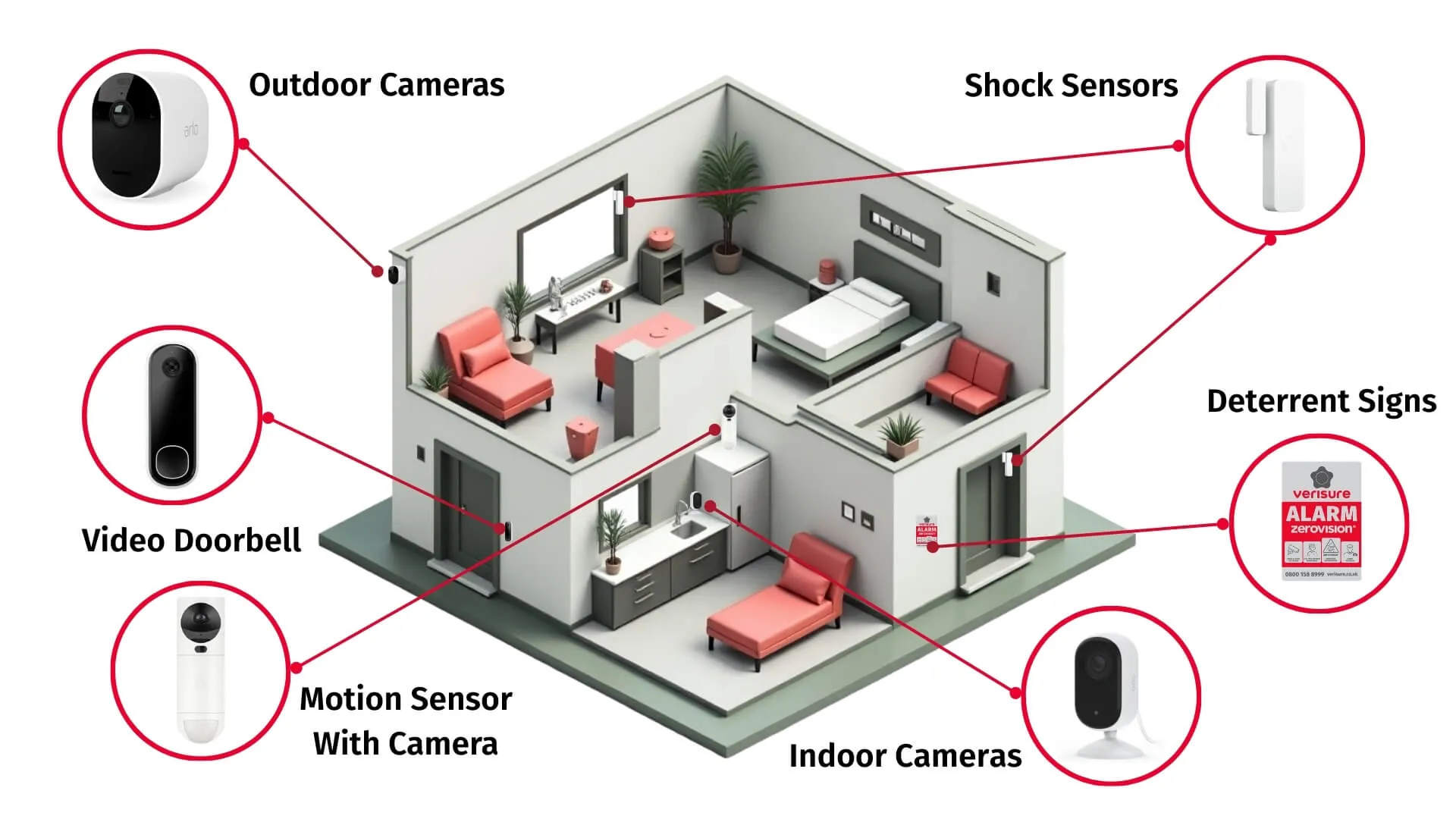
Security System Components and Functions
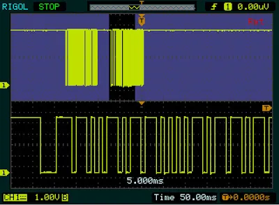
100 Oscilloscope Basics Q&A

Basic Requirements for Instrumentation Equipment
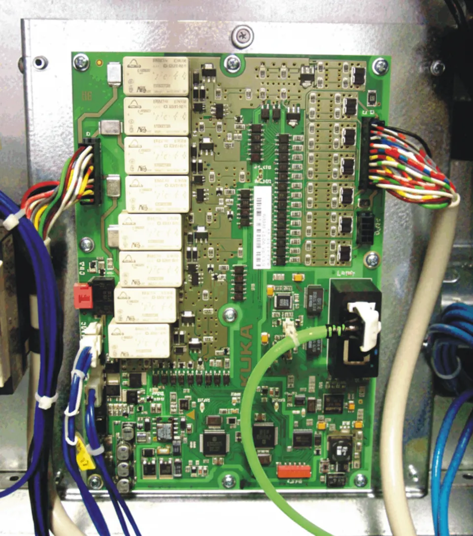
KUKA Robot X11 Field Wiring Overview
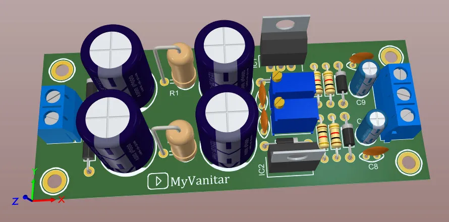
Designing Custom Filters for Audio Applications on PCBs: A Step by Step Tutorial

DDR4 3200 vs 3600: Differences and Compatibility
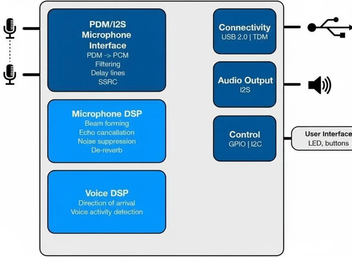
Inside Amazon Echo's Voice Control

Key Network Security Technologies