A 2-layer flexible circuit order measuring 38 × 12.5 mm at 0.32 mm finished thickness generated a focused set of engineering questions centered on an adhesive requirement. The customer requested that adhesive be applied, yet the documentation supplied no material designation, thickness, temperature rating, or adhesive system. Subsequent exchanges addressed production-file confirmation, stack-up verification, front-side placement feasibility, and a direct conflict between the adhesive outline and white silkscreen characters printed on the same side. The factory proposed relocating those characters to the reverse side and mirroring them. The records stop at the request for confirmation; no acceptance, file revision, or production result is documented.
Flexible PCB Order Specifications and Adhesive Requirements
The board ( #FPC-20260709-061 ) is specified as a single-piece 2-layer construction using rolled copper, with outer/inner copper listed as 1 OZ / 2 OZ, yellow solder mask on both sides, and white silkscreen on both sides. Surface finish is ENIG at 1.00, via treatment is via-cover-oil, hole size is 0.3 mm, and forming is by laser. Reinforcement is marked "none," electromagnetic film is none, and the back-adhesive category is recorded as strong adhesion. Quantity is 500 pieces. These parameters establish a thin flexible circuit whose total thickness budget is already constrained and whose back side carries a strong-adhesion designation, making the precise identity of any additional adhesive material consequential for both process compatibility and final stack-up.
In flexible-circuit manufacturing, adhesive commonly refers to a pressure-sensitive adhesive tape or release-lined film applied for mechanical attachment, temporary protection, or assembly positioning. Because the order already lists a strong-adhesion back category and zero reinforcement, the request to apply adhesive is consistent with a peel-and-stick or protective-tape function rather than a structural stiffener. The absence of a type designation, however, leaves open several process-critical variables: adhesive chemistry, liner type, thickness, peel strength, and maximum continuous or reflow temperature.
Unspecified Flexible PCB Adhesive Type and Material Requirements
The first engineering note states that the customer requires adhesive yet has not indicated which type is to be used. In CAM practice this is not a minor omission. Different commercial tapes differ in thickness by tens of microns, in peel adhesion by several N/25 mm, and in thermal endurance from roughly 100 °C continuous to higher short-term ratings. On a 0.32 mm finished board the added thickness of the adhesive layer directly affects the measured overall thickness, the laser-forming profile, and the clearance available for any subsequent assembly. An adhesive whose continuous rating is below the ENIG process or any planned reflow temperature can outgas, lose tack, or leave residue that interferes with solderability or electrical test.
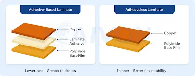
Figure 1: Adhesiveless vs Adhesive-based FPC
Because the back-adhesive category is already listed as strong adhesion, the missing specification also creates ambiguity about whether the requested adhesive is the same material, a protective liner over that material, or an additional layer on the opposite side. Without an explicit call-out, the CAM engineer cannot generate a reliable material stack or a cut file whose dimensions match the intended adhesive outline. The production-draft confirmation requested in the same communication therefore cannot be completed until the adhesive identity is resolved.
FPC Stack-Up Design and Adhesive Thickness Confirmation
A separate note asks the customer to confirm whether the prepared stack-up diagram is acceptable. For a 2-layer rolled-copper flexible circuit the stack-up normally comprises the copper foils, the dielectric substrate (commonly polyimide), any coverlay or solder-mask layer, and the adhesive or release film. With finished thickness specified at 0.32 mm and copper weights of 1 OZ and 2 OZ, the remaining dielectric and adhesive thicknesses must be calculated carefully so that the sum stays inside the stated tolerance. Adding an unspecified adhesive changes that arithmetic. The request for stack-up confirmation is therefore linked directly to the adhesive question: once the adhesive type and thickness are known, the diagram can be verified against the 0.32 mm target and against the yellow solder-mask and white silkscreen layers already defined.
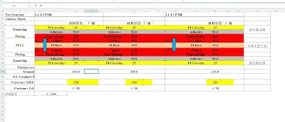
Figure 2: FPC stack-up diagram
Flexible PCB Adhesive Placement on the Front Side
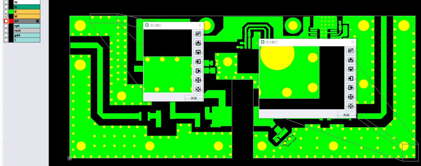
After the adhesive outline was generated from the customer drawing, the factory noted that the adhesive is positioned on the front side and asked whether that placement is feasible. Front-side application places the adhesive over the same surface that carries the yellow solder mask and the white silkscreen. In flexible-circuit process flow the adhesive tape is typically applied after surface finish and before or after laser forming, depending on whether the tape must survive the cutting operation or be applied to the already-cut piece. Alignment is performed to the board outline or to fiducials; any mismatch between the adhesive cut file and the actual copper or mask features can leave adhesive on pads or leave intended areas uncovered.
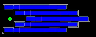
Figure 3: The adhesive tape made according to the drawing is on the front side
Flexible PCB Adhesive and Silkscreen Overlap: Relocation Options
The central manufacturing conflict is stated clearly: the customer requires the adhesive on the front side, yet the front-side characters overlap the adhesive area. The factory suggestion is to move the characters to the reverse side and mirror them, and to ask whether that change is acceptable.
White silkscreen on a yellow solder-mask background is the specified legend. When an adhesive layer is laminated over printed legend, several practical effects follow. The ink is no longer visible for assembly reference; the adhesive may not wet the ink surface as reliably as it wets the mask, producing local voids or reduced peel strength; and any subsequent cleaning or thermal cycle can lift the ink if the adhesive bond is stronger than the ink-to-mask bond. Because the order lists silkscreen on both sides, the reverse side is available. Mirroring the characters ensures that the text remains correctly oriented when the board is viewed from the reverse face. This is a routine CAM adjustment when legend conflicts with coverlay openings, adhesive outlines, or stiffener footprints, provided the legend content is not required to be readable from the front during assembly or test.
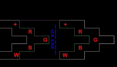
Figure 4: The characters on the front overlap with the tape
PCB Production File Confirmation and Outstanding Adhesive Issues
The communication sequence ends with repeated requests to confirm the production draft. In CAM workflow this confirmation normally follows resolution of open questions: material identity, stack-up approval, and any geometry changes such as the silkscreen relocation. Because the adhesive type is still unspecified and the silkscreen proposal is still pending, the draft confirmation is blocked by the same issues. Laser forming of a 0.32 mm board further requires that the adhesive cut file, if applied before forming, match the laser path within the process tolerance; an unresolved outline or thickness therefore also affects the forming program.
No subsequent messages, revised Gerbers, or material call-outs are present in the supplied records. The engineering status is therefore an open clarification request covering adhesive type, stack-up acceptance, front-side placement feasibility, and the proposed silkscreen relocation with mirroring.
Flexible PCB Manufacturing Challenges and CAM Considerations
The case illustrates a common flexible-circuit CAM intersection: an auxiliary material (adhesive) whose specification is incomplete, a placement that collides with an existing legend layer, and a thickness budget (0.32 mm) that cannot absorb an unknown adhesive thickness without verification. The factory's documented response—requesting the adhesive type, presenting a stack-up for review, noting the front-side location, and proposing a mirrored reverse-side legend—addresses each open item without assuming customer acceptance or process outcome. Further progress requires the missing material designation and an explicit decision on the silkscreen relocation before the production files can be confirmed.