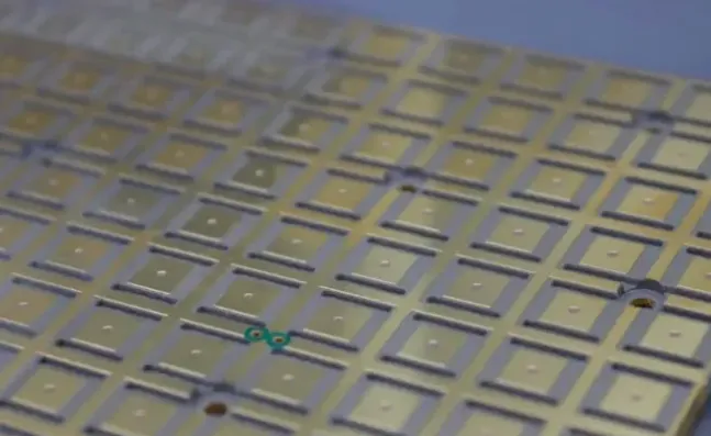
A flexible PCB that survives 50,000 bend cycles in the lab can still fail in the field when the base material does not match the actual combination of dynamic flexing, temperature exposure, or adhesive reliability requirements. In flexible printed circuits the base film is not merely a dielectric—it is the mechanical backbone and the primary limiter of long-term reliability. Unlike rigid boards, where the laminate mainly provides electrical isolation and structural support, the FPC base material must survive repeated or one-time bending while remaining dimensionally stable through soldering, humidity, and thermal cycling.
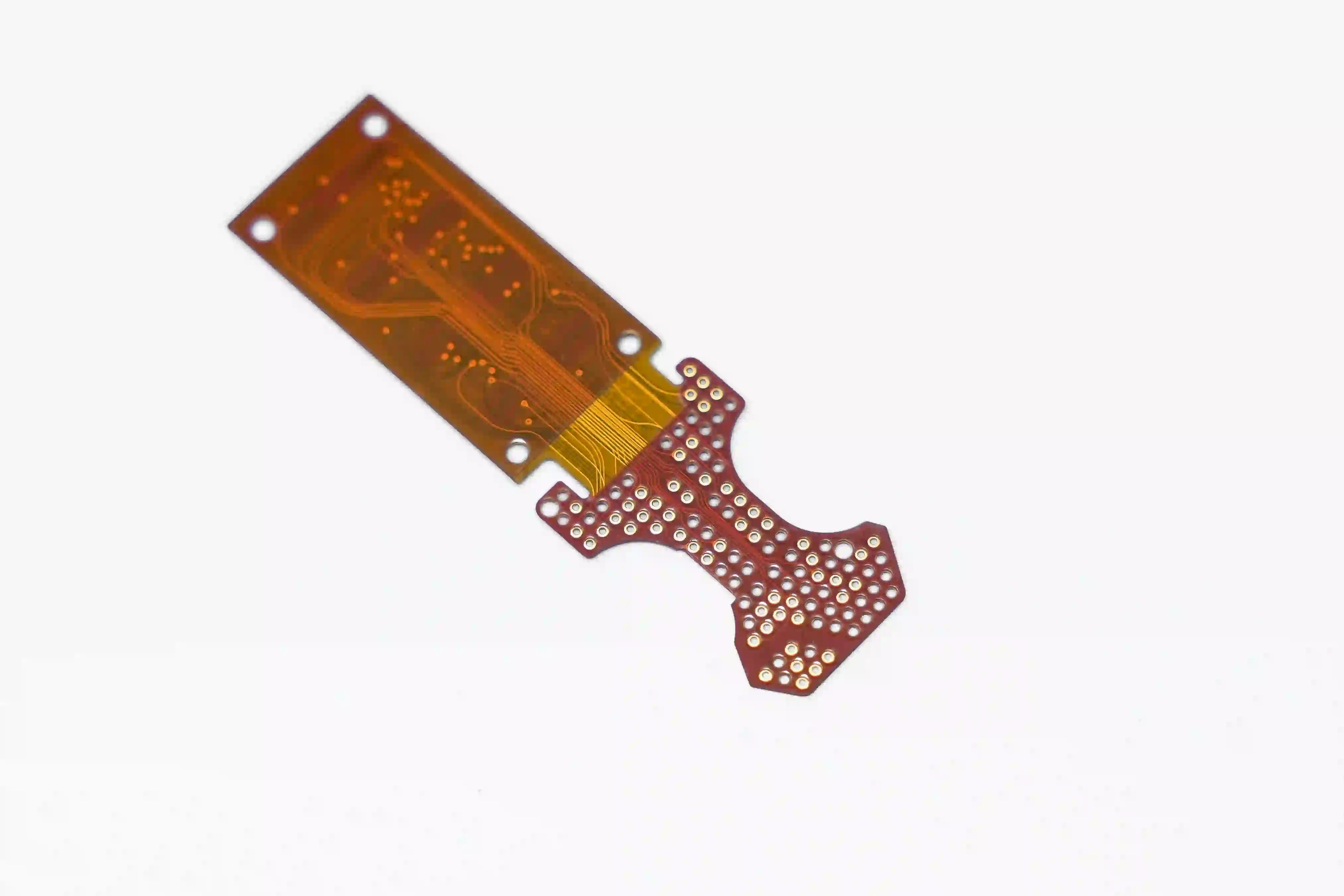
Material selection is therefore often more critical for flexible circuits than for rigid PCBs, because the substrate directly influences mechanical reliability, bending performance, and long-term durability. This guide delivers a clear comparison of the three primary commercial options used in production today, Polyimide (PI), PET (polyester), and adhesiveless constructions, along with the performance data that actually matters, a practical selection framework, and lessons drawn from real manufacturing experience. By the end you will have a decision checklist you can apply immediately to your next design.
Flexible PCB base materials are the thin polymer films that form the dielectric core of a flexible printed circuit and determine its bend performance, temperature rating, and long-term reliability.
What Is FPC Material?
FPC material refers to the materials used to build a flexible printed circuit. The most important material is the flexible dielectric substrate, which supports the copper circuit and provides electrical insulation.
Polyimide (PI) is widely used for applications that require a combination of flexibility, thermal performance, dimensional stability, and reliability. Polyester materials such as PET can be considered for applications with less demanding temperature and mechanical requirements.
However, an FPC is not made from a single material. A typical flexible circuit may combine a polymer substrate, copper foil, adhesive or adhesiveless bonding system, coverlay, and local stiffeners.
The right material combination depends on how the circuit will operate, how it will be manufactured, and what mechanical and environmental conditions it will experience.
Understanding Flexible PCB Base Materials and Stack-Up Fundamentals
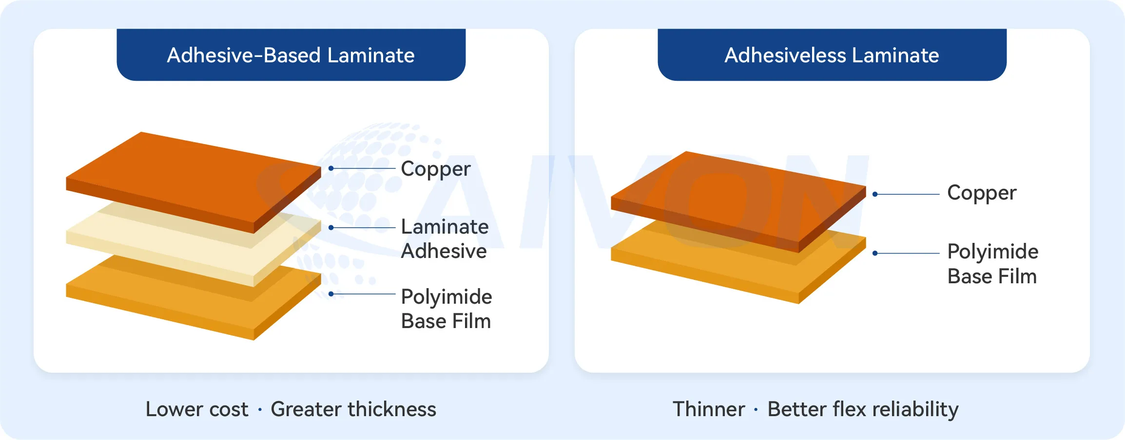
The FPC base material is the dielectric film that carries the copper circuit. In a conventional adhesive-based construction the typical stack-up runs: base film → adhesive → copper → coverlay (with its own adhesive). Adhesiveless constructions eliminate the adhesive layer between the base film and copper, producing a thinner, more homogeneous core.
Single-sided flexible circuits rely almost entirely on the base film for mechanical integrity. Double-sided and multilayer designs introduce additional copper and FPC coverlay layers, so the choice of base material influences overall thickness, neutral-axis placement, and residual stress after lamination and reflow. Because the base film dominates mechanical reliability, thermal performance, and cost, its selection sets the ceiling for the entire product.
Industry practice has evolved from purely adhesive-based constructions toward adhesiveless options as designs demand higher density, tighter bend radii, and longer dynamic flex life. Standards such as IPC-4202 (materials), IPC-6013 (qualification and performance), and IPC-2223 (design) provide the framework for evaluating these choices, but the final decision still rests on matching the film's intrinsic properties to the application's flex regime and environmental envelope.
Types of Flexible PCB Materials: PI, PET, PEN, and Adhesiveless FPC
The most common substrates for flex PCBs are polyimide, polyester (PET), and polyethylene naphthalate (PEN), each offering distinct profiles suited to different demands. Polyimide stands out for its superior thermal and chemical resistance, making it ideal for environments with elevated temperatures or harsh chemicals.
PET provides a balance of flexibility and economy, commonly used where cost constraints dominate and operating conditions are mild. PEN bridges the gap, delivering improved dimensional stability over PET while remaining more affordable than polyimide. These materials form the base dielectric layer, typically laminated with copper foil, and their selection drives the flex PCB material comparison. In commercial FPC production, PI-based constructions (including adhesive and adhesiveless structures) and PET represent the dominant choices, while PEN serves as a niche intermediate option.
|
Material |
Position |
Typical Usage |
|---|---|---|
|
PI |
High reliability |
Automotive, medical |
|
PET |
Cost optimized |
Consumer |
|
PEN |
Middle option |
Sensor |
|
Adhesiveless PI |
Premium performance |
Dynamic flex |
Polyimide (PI) Flexible PCB Materials
Polyimide quickly became the industry standard for high-reliability flexible circuits because its aromatic polymer structure delivers exactly what most FPC applications need: robust thermal performance, strong mechanical stability, excellent chemical resistance, and solid high-frequency capability.
On the thermal side, PI stands out by comfortably handling continuous operating temperatures in the 150–200 °C range and short-term peaks well above 260 °C. This makes it fully compatible with standard lead-free reflow soldering—something many competing materials simply cannot manage without deforming or degrading.
Mechanically, it offers excellent dimensional stability across temperature changes and repeated bending cycles. The film resists excessive shrinkage or expansion, which helps keep traces aligned and reduces built-in stress in the final assembly, whether the design is single-layer or complex multilayer.
Chemically, PI is highly resistant to fluxes, cleaning solvents, conformal coatings, and many harsh operating environments. This durability protects the circuit over its full service life, especially in automotive, industrial, or medical applications where exposure to aggressive substances is common.
For high-frequency work, PI also performs well with stable dielectric properties that support good signal integrity and impedance control in RF and fast digital designs.
PET (Polyester) Flexible PCB Materials
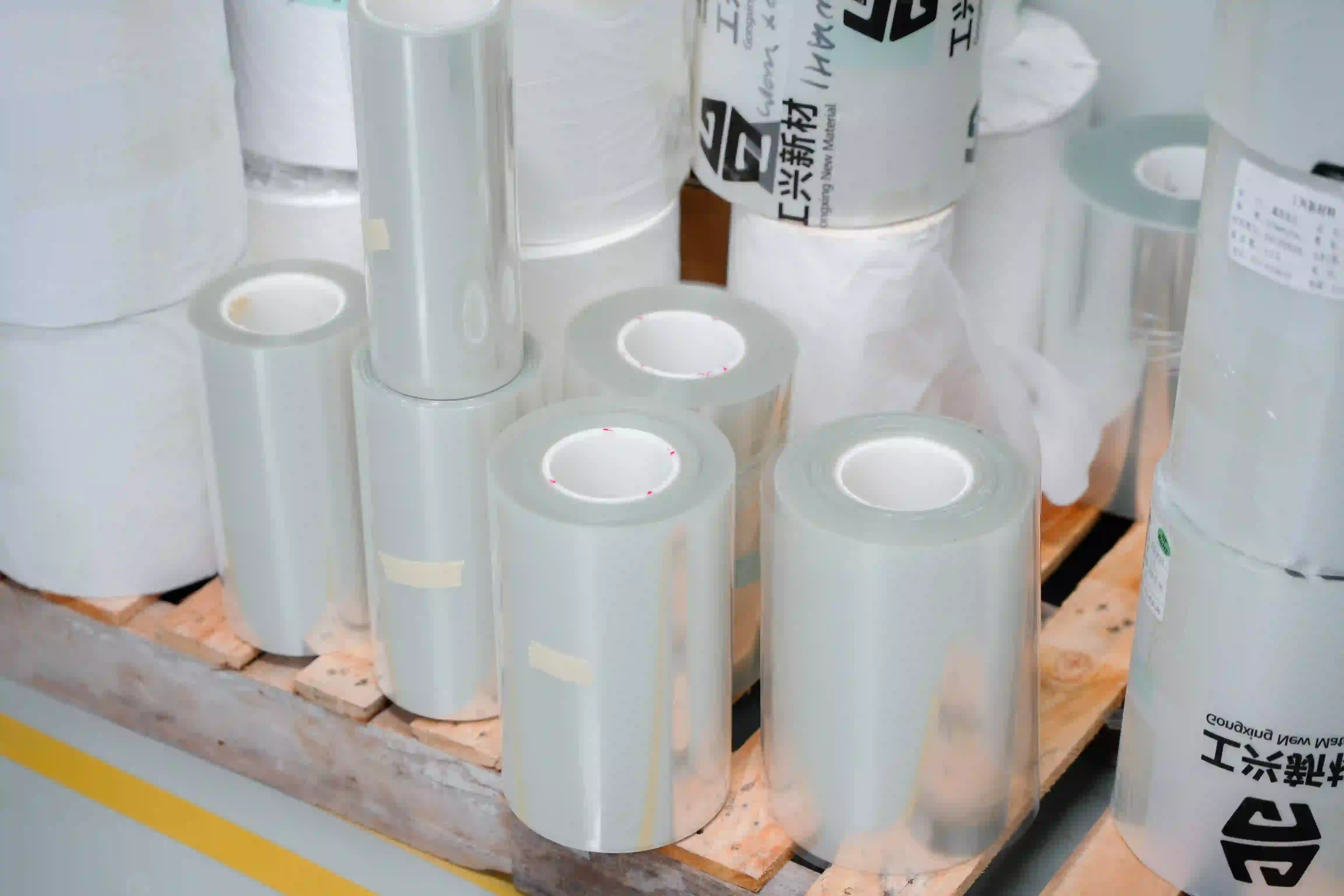
PET is selected when cost is the dominant driver and the application remains static or experiences only limited flexing at moderate temperatures. Continuous use is generally limited to 80–105 °C; short-term exposure above 150 °C risks softening and dimensional shift. PET offers good initial flexibility, lower moisture absorption (<0.8 %), and a clear or translucent appearance that can be advantageous in certain optical or consumer designs. Typical thicknesses start at 25 µm. Because standard reflow soldering exceeds its thermal capability, PET circuits usually rely on low-temperature soldering, conductive adhesives, or mechanical connectors.
Adhesiveless (Adhesive-Free) Flexible PCB Materials
In adhesiveless constructions copper is directly bonded or plated onto the polyimide film without a separate adhesive layer. FPC manufacturing process include casting the polyimide onto copper, sputtering a seed layer followed by electrolytic plating, or specialized lamination processes. The resulting core is thinner, more homogeneous, and free of the adhesive's lower thermal and mechanical limits. Benefits include improved heat dissipation, higher dynamic flex life, tighter minimum bend radii, better plated-through-hole reliability in multilayer designs, and more consistent impedance control. The trade-off is higher material cost and sometimes longer lead times.
Polyimide vs PET Flex PCB: A Head-to-Head Comparison
Polyimide excels in high temperature flex PCB materials applications due to its inherent stability across wide thermal ranges and excellent dielectric properties. It maintains integrity during soldering and reflow processes, resisting shrinkage or expansion that could stress traces. PET, as a cost-effective flex PCB material, offers good initial flexibility and transparency but falls short in sustained heat exposure, limiting it to lower-temperature assemblies. Polyimide's higher modulus provides better resistance to creep over time, whereas PET may exhibit more dimensional changes under humidity. In terms of cost, PET significantly undercuts polyimide, making it attractive for high-volume, static flex-to-install designs.
Mechanical performance further differentiates them: polyimide supports tighter bend radii and repeated minor stresses if needed, aligning with IPC-2223 design guidelines for flexible boards. PET performs adequately for single-bend applications but risks brittleness after prolonged exposure to moderate heat. Chemical resistance favors polyimide in industrial settings, while PET suffices for consumer electronics. Electrical characteristics, including low dielectric loss, are strong in both, but polyimide edges out in high-frequency signals. Factory qualification often involves IPC-TM-650 tests to confirm these traits before full-scale production.
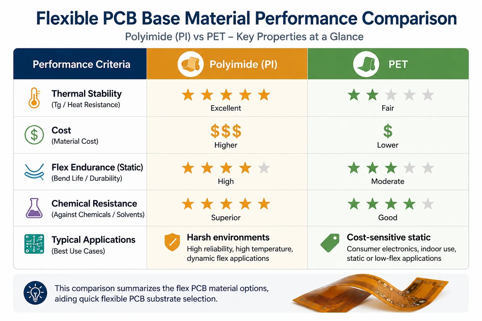 PI vs PET vs Adhesiveless FPC: Complete Material Comparison
The table below consolidates the properties that most directly influence field reliability and manufacturability.
|
Property |
Adhesive PI |
PET |
Adhesiveless PI |
|---|---|---|---|
|
Continuous operating temperature |
150–200 °C |
80–105 °C |
150–200+ °C |
|
Short-term peak temperature |
>260 °C (reflow capable) |
~150 °C |
>260–300 °C |
|
Dielectric constant (1 MHz) |
≈3.4 |
≈3.0–3.2 |
≈3.4 |
|
Dissipation factor (1 MHz) |
≈0.01 |
≈0.018 |
≈0.008–0.01 |
|
Tensile strength / elongation |
High / 60–80 % |
Moderate / >100 % |
Higher / 40–70 % |
|
Moisture absorption (24 h) |
1.5–2.9 % |
<0.8 % |
0.8–1.5 % (lower in many grades) |
|
Chemical resistance |
Excellent |
Good |
Excellent |
|
Dimensional stability (CTE) |
~20 ppm/°C |
~27 ppm/°C |
~20 ppm/°C (superior Z-axis) |
|
Typical bend radius capability |
Static: 6–12× thickness Dynamic: moderate |
Static preferred; limited dynamic |
Static: tighter Dynamic: 2–5× better life |
|
Relative cost index |
1.0 |
0.3–0.5 |
1.4–1.8 |
|
Common application suitability |
High-rel static & dynamic, automotive, medical, industrial |
Cost-driven static consumer, sensors, disposables |
High-density dynamic flex, wearables, fine-pitch, high-temp |
For wearables and foldable devices that demand >100 000 dynamic cycles at tight radii, adhesiveless PI is usually the only practical choice. Automotive interior controls with moderate temperature and mostly static flex often stay with adhesive PI for its reliability margin over PET. Cost-sensitive, low-temperature, single-bend consumer products can safely use PET once temperature and chemical exposure limits are confirmed. Medical disposables frequently evaluate PET after verifying biocompatibility and limited flex requirements.
Choose adhesive PI when the dominant requirement is proven high-temperature reliability at moderate cost. Choose PET when the dominant requirement is lowest cost under strictly controlled temperature and static flex. Choose adhesiveless PI when the dominant requirement is maximum dynamic flex life, minimum thickness, or highest density.
How Flexible Base Material Choice Affects Bend Life and Dynamic Flex Performance
In real-world flexible circuits, fatigue failure almost always starts with the copper traces cracking long before the base film itself ruptures. You see this pattern repeatedly in dynamic applications, whether in wearables, automotive sensors, or medical cables, where the board undergoes thousands or hundreds of thousands of bend cycles. The copper simply fatigues under repeated strain while the polyimide film remains largely intact.
This happens because the mechanical strain during bending is not distributed evenly. The base film's thickness and modulus play a major role, but the biggest influence often comes from the construction details around the copper. In traditional adhesive-based designs, the adhesive layer sits between the polyimide film and the copper. This adhesive is a much softer, lower-modulus material compared to both the copper and the PI film. During each bend, it creates a "weak interface" that concentrates cyclic strain right at the copper-adhesive boundary, turning it into a preferred site for micro-cracks to initiate and propagate over time.
Adhesiveless constructions avoid this problem entirely by bonding the copper directly to the polyimide film. With no soft adhesive layer to act as a strain concentrator, the stress distribution becomes more uniform. As a result, the same overall board thickness often delivers 2–5× dynamic flex life compared to adhesive-based equivalents. The improvement is especially noticeable at tighter bend radii.
Of course, the base material choice does not act in isolation. Design rules interact strongly with it. Proper neutral-axis placement (balancing copper layers or adjusting coverlay thickness to keep the copper near the neutral plane), selecting rolled-annealed (RA) copper for its superior ductility and elongated grain structure, and tightly controlling coverlay thickness can all amplify the inherent advantages of the chosen film. Conversely, poor implementation can negate them.
In practice, the most reliable way to confirm performance remains IPC bend-endurance testing per IPC-TM-650. Always specify the exact bend radius, cycle rate, and total cycles to match your product's real-world use conditions rather than relying on generic lab numbers.
Choosing FPC Materials for Different Applications
Material selection becomes easier when the application requirements are clearly defined.
The following examples show how the priorities can change between different product categories.
FPC Materials for Wearable Electronics
Wearable electronics often require thin, lightweight, and flexible circuit structures.
The FPC may need to follow curved product surfaces or move with the surrounding mechanical structure. Material selection should therefore consider flexibility, thickness, environmental exposure, and the expected mechanical movement.
Polyimide is commonly considered when the application requires a combination of flexibility and reliability.
FPC Materials for Automotive Electronics
Automotive applications can expose flexible circuits to temperature changes, vibration, moisture, and mechanical stress.
The appropriate FPC material should therefore be selected based on the actual installation location and operating environment.
For automotive electronics, thermal performance, dimensional stability, environmental resistance, and long-term reliability may be more important than minimizing material cost.
FPC Materials for Medical Devices
Medical electronics can require compact and flexible circuit structures because electronic modules may need to fit into small or ergonomically shaped devices.
Material selection should consider the specific operating environment, mechanical requirements, temperature conditions, and product-level material compatibility.
For medical applications, material decisions should be made according to the requirements of the finished device rather than simply choosing a material based on its general reputation.
FPC Materials for Consumer Electronics
Consumer electronics often require a combination of compact size, flexibility, manufacturability, and cost efficiency.
FPCs can help connect modules in smartphones, cameras, displays, tablets, wearables, and other compact products.
The appropriate material depends on whether the circuit is stationary, occasionally bent, or repeatedly flexed during normal operation.
FPC Materials for High-Temperature Applications
High-temperature applications require particular attention to the complete FPC material system.
Polyimide is often considered for applications where thermal performance is important. However, the substrate is not the only factor that determines high-temperature reliability.
Copper, adhesives, coverlay, surface finish, stiffeners, and assembly conditions should also be evaluated to ensure that the complete construction is suitable for the application.
How to Choose the Right FPC Material
Material selection is where most engineers spend the real decision-making effort, because it directly balances performance, reliability, cost, and manufacturability. Rather than treating it as a simple catalog lookup, experienced teams follow a structured yet practical process that incorporates both technical requirements and real production realities.
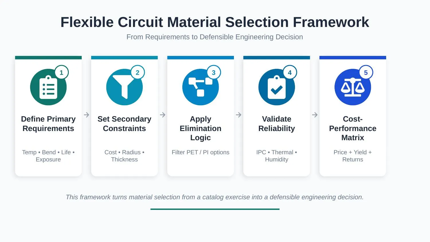
Start by clearly defining your primary operating requirements: What is the maximum continuous and peak temperature the circuit will see? Is the flex regime static or dynamic? How many cycles are expected over the product lifetime? What chemical or humidity exposure will it face in the field?
Next, list your secondary constraints: target cost per unit, minimum bend radius, overall thickness limits, impedance control needs, and any regulatory or biocompatibility requirements. This step often reveals the real trade-offs early.
With requirements in hand, apply straightforward elimination logic:
If you are selecting FPC material for extreme temperatures (regularly exceed ~105–120 °C) or the design involves meaningful dynamic flexing, eliminate PET right away.
When you need the highest dynamic flex life combined with the thinnest possible stack-up, prioritize adhesiveless PI constructions.
For cost-sensitive, static or limited-flex consumer products operating in mild conditions, PET or standard adhesive-based PI become the leading candidates.
Once you have narrowed the options, move to validation. Build prototypes and run targeted reliability tests—IPC bend-endurance testing at your actual design radius and cycle rate, thermal cycling, humidity-bias tests, and post-reflow peel-strength checks. These steps catch most hidden issues before volume production.
In parallel, build a simple cost-versus-performance matrix. Look beyond raw material price to include expected field-return costs, assembly yield impact, and processing complexity. For budget-conscious designs, PET shines in high-volume static applications like consumer sensors or simple interconnects because its lower material cost and compatibility with standard equipment deliver real savings. However, always validate thermal margins through prototyping—many teams have learned the hard way that pushing PET too close to its limits creates hidden reliability risks. PEN can serve as a useful middle-ground option when you need slightly better moisture resistance without jumping fully to PI pricing.
Finally, adopt a few best practices that separate successful projects from problematic ones: consult IPC-2223 early for bend-radius and stack-up guidelines, engage your fabricator during the material selection phase to align on processing windows (etch factors, lamination parameters, etc.), and thoroughly document the rationale and trade-offs in your design review. Iterate based on test data rather than assumptions.
This approach turns material selection from guesswork into a defensible engineering decision that holds up both in the lab and in the field.
AIVON Manufacturing Experience and Application Case Insights
In typical production scenarios the following patterns recur. At AIVON, material selection discussions typically begin with application requirements rather than material cost alone. Engineers evaluate flex cycles, operating temperature, stack-up constraints, and assembly conditions before recommending a suitable construction.
Wearable devices requiring more than 100 000 dynamic bend cycles at tight radii almost invariably move to adhesiveless PI. The decisive factors are usually the combination of RA copper, precise neutral-axis control, and reduced overall thickness; adhesive-based constructions of equivalent thickness simply do not deliver the required cycle life.
Cost-driven automotive interior switch panels with moderate temperature and largely static flex commonly stay with standard adhesive PI. The reliability margin over PET, especially resistance to long-term humidity and occasional thermal spikes, justifies the modest cost increase and reduces the risk of warranty returns.
Medical disposable sensors with strict biocompatibility requirements and limited flex frequently evaluate PET after confirming that peak temperatures stay well below the material's limit and that chemical exposure (sterilization agents, body fluids) remains within its capability. When those conditions are met, PET delivers acceptable performance at substantially lower cost.
Common failure modes observed when material selection is mismatched include delamination at the adhesive–film interface after thermal cycling, copper fatigue cracking in dynamic regions, and dimensional shift during reflow that causes registration errors or solder-joint stress. Experienced manufacturers therefore maintain a material qualification matrix, enforce incoming inspection of moisture content and peel strength, and require full stack-up documentation that includes copper type, coverlay thickness, and intended flex regime. These controls prevent the majority of field returns that can be traced to base-material decisions.
Conclusion
The right FPC material provides the foundation for a reliable flexible circuit.
Polyimide is a common choice when thermal performance, flexibility, dimensional stability, and reliability are important. PET and PEN can be considered for applications with different performance and cost requirements, while adhesiveless constructions may be suitable for specific high-performance or compact designs.
Material selection should always start with the actual application. Operating temperature, bending behavior, electrical requirements, environmental conditions, manufacturing processes, and cost should all be considered before choosing an FPC substrate.
Specialized materials such as Kapton® B can also be useful when an application requires specific characteristics such as black appearance, opacity, or laser-processing compatibility.
For complex flexible circuit projects, working with an experienced manufacturer can help connect material selection with DFM, fabrication, assembly, and production requirements. AIVON provides custom flexible PCB manufacturing and engineering support for projects from prototype development to production.
FAQs
Q1: What is the maximum continuous operating temperature for PET flexible PCB materials?
A1: Most commercial PET films are rated for continuous use between 80 °C and 105 °C. Short-term peaks above 150 °C risk softening and permanent dimensional change. Always confirm the specific grade with the material supplier.
Q2: Can adhesiveless PI completely replace traditional adhesive-based PI in all applications?
A2: No. Adhesiveless constructions excel in dynamic flex, thickness-critical, and high-temperature designs, but the higher cost is not justified for many static, cost-sensitive applications where adhesive PI already meets reliability targets.
Q3: Is there a significant difference in impedance control between adhesive and adhesiveless constructions?
A3: Yes. Adhesiveless cores provide a more homogeneous dielectric, resulting in tighter impedance tolerance and lower dissipation factor, which is advantageous for high-speed or controlled-impedance designs.
Q4: What reliability tests should be specified when qualifying a new FPC base material?
A4: The minimum qualification set includes IPC-TM-650 flex-endurance testing at the design bend radius and cycle rate, thermal cycling, humidity-bias insulation resistance, peel strength after reflow simulation, and dimensional stability after baking and soldering.
Q5: Can PI and PET be mixed in the same multilayer flexible circuit?
A5: It is rarely practical. The large differences in thermal expansion, processing temperatures, and moisture behavior create residual stress and process-window conflicts. As a result, hybrid constructions are almost always avoided.
Q6: What makes PET a popular choice for cost-effective flex PCB materials?
A6: PET delivers adequate static bend performance at a fraction of polyimide's cost, making it well suited for high-volume consumer electronics. It is easy to process in standard manufacturing environments and offers good initial adhesion and transparency. Although its lower thermal resistance limits use in demanding applications, it remains an economical choice when cost is a higher priority than maximum durability.
Q7: What are the best applications for Kapton B in flexible circuit manufacturing?
A7: The best applications for a Kapton-based flexible circuit material depend on the specific material grade and the requirements of the circuit. Polyimide materials are commonly considered for flexible circuits used in applications that require thermal stability, flexibility, and reliable electrical insulation. Automotive, medical, industrial, wearable, and other compact electronic systems may use polyimide-based flexible circuits. Designers should confirm the material grade and manufacturer's specifications before selecting it for a specific application.
Q8: What are the best industries for Kapton B flexible circuit materials?
A8: Kapton-based flexible circuit materials can be considered across industries such as automotive electronics, medical devices, consumer electronics, wearables, telecommunications, and industrial equipment. The appropriate material depends on factors such as operating temperature, flexibility, mechanical stress, electrical requirements, and environmental conditions.