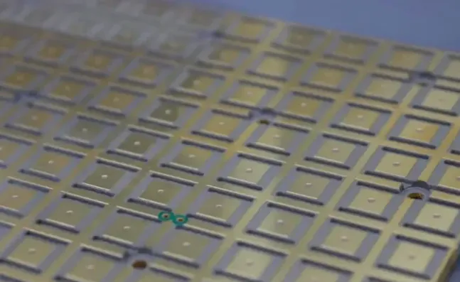
In flexible circuit production, incorrect FPC coverlay selection or processing ranks among the top causes of field failures. Delamination after repeated bending, adhesive that squeezes onto pads and ruins solderability, window openings that misalign by tens of microns, or premature cracking in dynamic-flex zones. These problems appear after assembly and cost far more than the material itself.
The coverlay must deliver electrical insulation, mechanical protection, and environmental barrier performance while surviving continuous flexing without adding excessive stiffness or stress concentrations. That combination is far more demanding than rigid-board solder mask. Get the adhesive chemistry wrong and the circuit either fails early under flex life testing or cannot survive the required operating temperature. Get the lamination process wrong and voids or wrinkles become the starting points for delamination.
Highlights
● Choose acrylic adhesive polyimide coverlay when dynamic flex life and tight bend radius dominate.
● Choose epoxy adhesive systems when continuous temperature above ~120 °C or chemical resistance is the priority.
● Laser window opening delivers tighter registration than mechanical die cutting for fine-pitch pads.
● Coverlay thickness (polyimide + adhesive) directly governs minimum FPC bend radius and overall stack-up flexibility.
This guide gives engineers the practical ability to select the correct polyimide coverlay, specify lamination parameters, control window precision, and avoid the defects that destroy yield and reliability.
What is FPC Coverlay?
FPC coverlay is a pre-cut polyimide film coated with a thermosetting adhesive, almost always acrylic or epoxy, that is laminated onto the etched flexible circuit. It replaces the liquid photoimageable solder mask used on rigid boards. The construction is simple: a polyimide film layer (commonly 12.5 µm, 25 µm or 50 µm), an adhesive layer of matching or greater thickness, and a release liner that is removed before lamination.
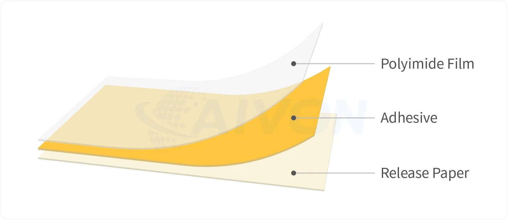
Its job is fourfold. It electrically insulates the copper traces. It protects against abrasion and handling damage. It forms a barrier against moisture, chemicals and flux residues. And through precision openings it selectively exposes pads, test points and component sites while fully encapsulating the surrounding circuitry.
Compared with liquid photoimageable (LPI) solder mask, coverlay is mandatory for most dynamic-flex applications, tight bend radii, high-reliability medical or automotive circuits, and any design that must meet the more stringent flex-life requirements of IPC-6013. LPI can be acceptable for static or very low-flex consumer circuits where cost and fine-feature resolution matter more than long-term mechanical durability. Once the circuit must survive thousands or tens of thousands of bend cycles, or when the minimum bend radius approaches the limits of the material stack, polyimide coverlay becomes the reliable choice.
FPC Coverlay Materials: Acrylic vs Epoxy Adhesive Systems
The polyimide film itself is rarely the differentiator. Almost every high-reliability FPC uses PI because of its thermal stability, mechanical toughness and dimensional performance. The adhesive chemistry is what engineers actually choose.
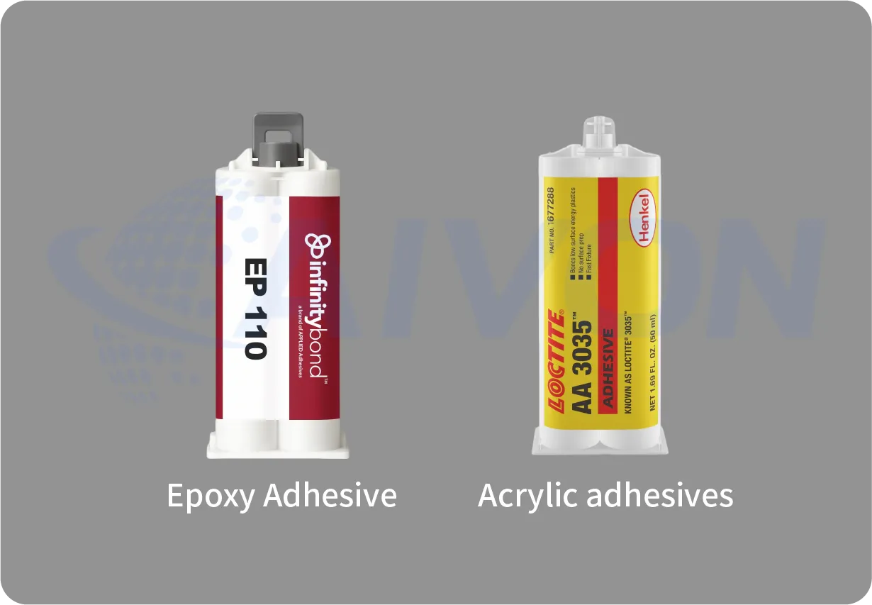
Acrylic Adhesive for FPC Coverlay
Acrylic adhesive systems deliver excellent flexibility and elongation. They flow well during lamination, filling the valleys around etched copper features and producing reliable encapsulation. Continuous operating temperature is typically rated around 105 °C for standard grades, though modified formulations can go higher. Peel strength is usually in the 1.0–1.5 N/mm range. Shelf life is longer and storage conditions are more forgiving. These properties make acrylic coverlay the default for the dynamic FPC, wearable devices, foldable consumer electronics and any application where repeated bending or a tight bend radius is the dominant requirement.
The trade-offs are real. Insulation resistance can be slightly lower than epoxy systems. Under prolonged high-temperature bias there is a greater risk of copper migration. Chemical resistance in aggressive solvent or flux environments is weaker.
Acrylic Adhesive for FPC Coverlay
Epoxy adhesive systems reverse the priorities. Continuous temperature ratings of 140–155 °C are common. Chemical and solvent resistance is stronger. Bond strength is often higher and dimensional stability after lamination is better. These characteristics suit automotive under-hood environments, industrial controls, higher-temperature rigid-flex designs and circuits exposed to harsh chemicals.
The cost is reduced flexibility compared with acrylic, a shorter shelf life, and greater sensitivity to storage conditions and pressing parameters. Epoxy systems generally require tighter process control during lamination.
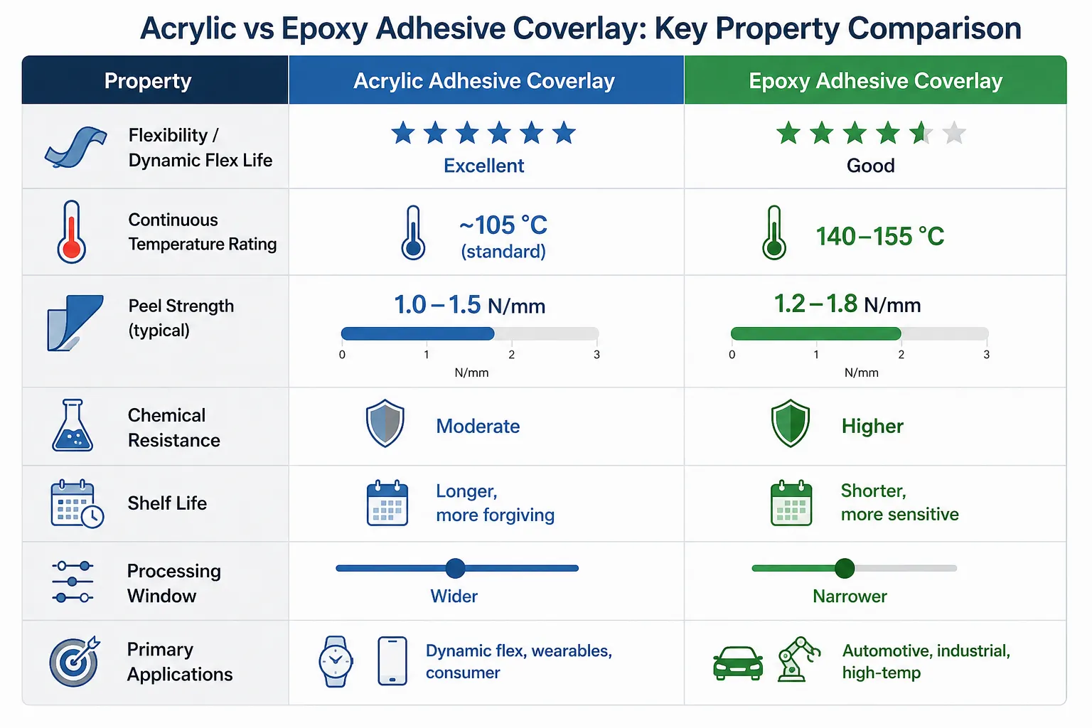
Choose acrylic when flex life and bend radius dominate the requirements. Choose epoxy when temperature rating or chemical exposure dominates. Specialty systems, such as polyimide adhesives or adhesiveless constructions, low-flow formulations, exist for extreme cases, but they add cost and complexity that most designs do not need.
FPC Coverlay Thickness Guide: Film, Adhesive and Flexibility Impact
Common Flex PCB Coverlay Thicknesses:
|
Name |
Polyimide Thickness μm (mil) |
Adhesive Thickness μm (mil) |
|---|---|---|
|
13/15 |
13 (0.5) |
15 (0.6) |
|
13/25 |
13 (0.5) |
25 (1.0) |
|
25/25 |
25 (1.0) |
25 (1.0) |
|
25/35 |
25 (1.0) |
35 (1.4) |
|
25/50 |
25 (1.0) |
*50 (1.0) |
FPC Coverlay thickness is not a free variable. The polyimide film thickness plus the adhesive thickness sets both the mechanical protection and the minimum bend radius of the finished circuit. Common constructions are 13 µm/25 µm, 25 µm/25 µm, and 50 µm film with matching or thicker adhesive for heavier copper or higher dielectric strength.
Thinner coverlay reduces overall stack height and improves flexibility, which is essential for dynamic applications. Thicker coverlay improves abrasion resistance and dielectric performance but increases the neutral-axis distance and therefore the strain on the copper during bending. A practical rule of thumb for adhesive thickness is roughly 25 µm of adhesive per ounce of copper to ensure full encapsulation without excessive squeeze-out.
Adhesive flow characteristics matter just as much as thickness. Acrylic systems tend to flow more readily, which helps fill fine features but increases the risk of pad contamination if the process window is not controlled. Epoxy systems flow less, reducing squeeze-out risk but raising the chance of incomplete encapsulation on circuits with significant topography.
Thermal and mechanical reliability also depend on CTE match and residual stress after lamination. Poor control of the temperature-pressure profile leaves residual stress that later appears as delamination under thermal cycling or repeated flexing. Electrical requirements, dielectric strength and insulation resistance, become critical on fine-pitch or higher-voltage Flex PCB design; here the higher-temperature epoxy systems often provide more margin.
Cost and supply-chain factors close the loop. Standard 25 µm/25 µm acrylic constructions are widely available and relatively inexpensive. Custom thicknesses, epoxy systems or specialty films carry longer lead times and higher material cost, plus the logistical burden of managing shorter shelf life.
Coverlay Thickness for Different FPC Applications
The appropriate coverlay thickness depends on the application. Static flex circuits may prioritize protection and insulation, while dynamic flex circuits require closer attention to flexibility and repeated bending.
In rigid-flex PCBs, the coverlay construction also needs to work with the flexible section and the transition to the rigid board. For compact wearable devices, overall thickness and mechanical flexibility may be important design considerations.
Rather than choosing a universal thickness, engineers should confirm the suitable construction with the FPC manufacturer based on the actual design and application requirements.
FPC Coverlay Lamination Methods and Process Control
The application sequence is straightforward on paper: FPC material preparation and drying, precision opening of windows, alignment to the circuit, lamination under heat and pressure, optional post-cure, and inspection. Execution quality separates high-yield lines from chronic scrap problems.
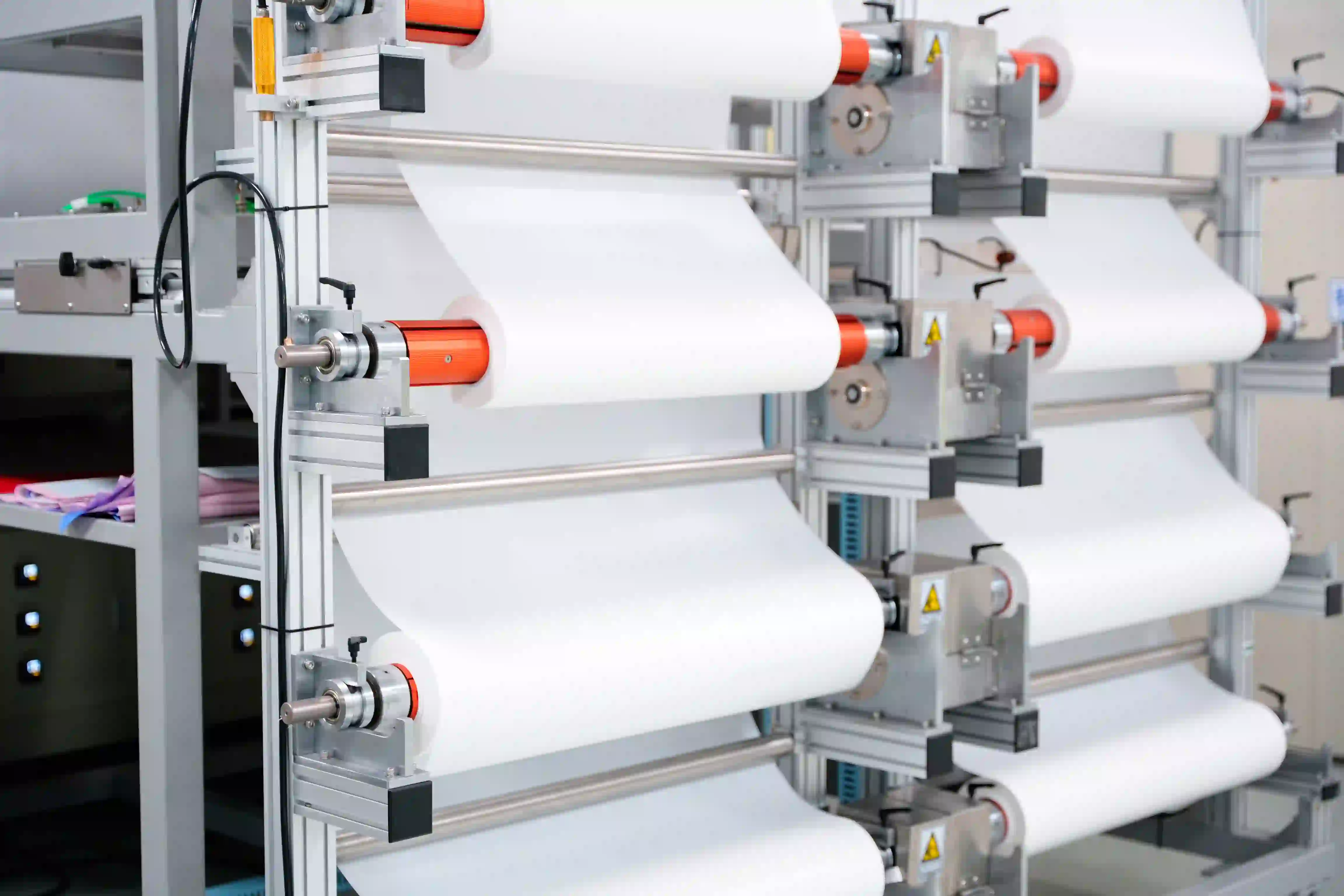
Roll-to-roll (hot-roll) lamination is continuous and high-throughput. It works well for simple single-sided or low-complexity circuits. Typical parameters sit in the 160–200 °C range with controlled pressure and line speed. The method is fast and cost-effective at volume, but it is more prone to trapped air, wrinkles and uneven adhesion on circuits that have significant topography or that are double-sided.
Vacuum press (or autoclave-style) lamination removes air before pressure is applied. It produces superior conformity on double-sided, multi-layer or high-topography circuits and dramatically reduces voids and wrinkles. Throughput is lower and equipment cost higher, yet for complex rigid-flex or high-reliability work the FPC manufacturing defect reduction usually justifies the choice. In production environments that handle both simple and complex flex, vacuum capability is often the difference between acceptable and excellent yields.
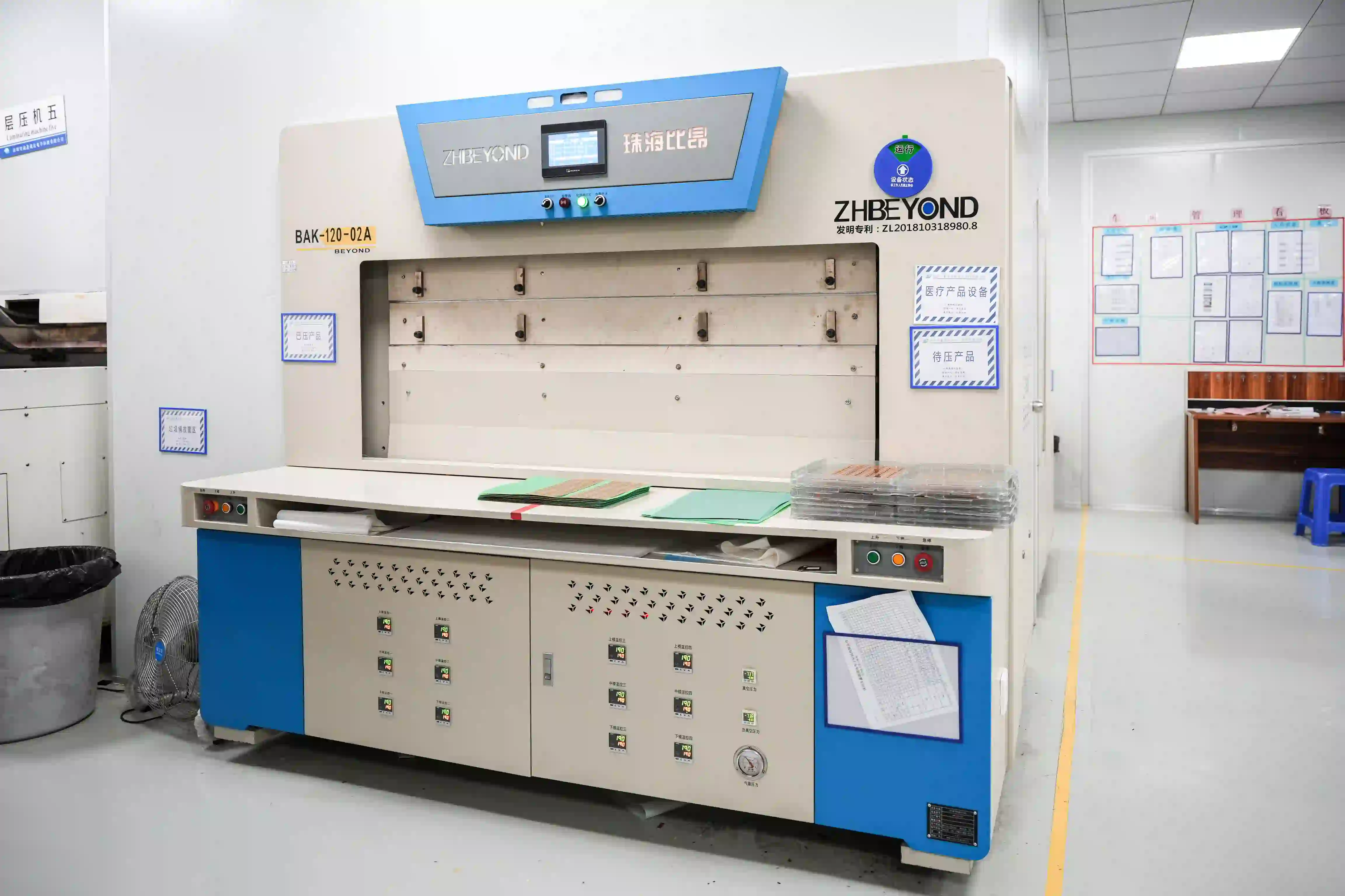
Process windows are material-specific. Temperature, pressure, dwell time and the choice of release films or silicone pads all interact. Over-pressing drives adhesive squeeze-out; under-pressing leaves voids. Post-bake is sometimes required to complete cross-linking, particularly with certain epoxy systems.
FPC Coverlay Window Opening Precision and Design Rules
Windows are opened before lamination, either by mechanical die cutting/punching or by laser (CO₂ or UV). Die cutting is economical for high-volume simple geometries. Laser cutting provides tighter registration and is preferred for fine-pitch pads and complex patterns.
Registration tolerance to the copper pads is critical. Typical realistic laser registration is in the range of ±50–75 µm under controlled conditions; mechanical methods are usually looser. Design rules that improve yield include adequate annular ring around pads, optimizing FPC coverlay window sizing rather than using 1:1 pad ratios (accounting for adhesive flow), and the use of alignment fiducials that the fabricator can actually see and use. Insufficient annular ring or aggressive window sizing leads to adhesive that either covers part of the pad or leaves unprotected copper at the edge, both of which create downstream soldering or reliability problems.
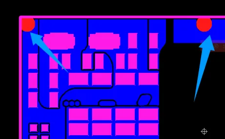
FPC coverlay opening precision directly affects solderability, component placement accuracy and electrical test access. Poor windows are a frequent source of customer returns that are expensive to diagnose after assembly.
How to Choose the Right FPC Coverlay
Start with the mechanical requirements:
● Is the circuit static or dynamic?
● What is the minimum bend radius and the required number of flex cycles?
Dynamic applications with tight radii almost always favor acrylic systems and thinner constructions.
Next define the thermal and environmental envelope:
● Continuous operating temperature above approximately 120 °C or exposure to aggressive chemicals points toward epoxy.
● Humidity and moisture resistance should also be considered, although both adhesive families can be formulated for good barrier performance.
Then examine electrical and density needs:
● Fine-pitch or higher-voltage designs may require thicker dielectric or higher insulation resistance; this can influence both thickness and adhesive choice.
Manufacturing constraints close the decision:
● Single-sided simple circuits can often run roll-to-roll with acrylic.
● Double-sided or multi-layer circuits with significant topography benefit from vacuum lamination and may tolerate either adhesive depending on the thermal needs.
Volume and cost targets influence whether standard or custom constructions are justified.
Application examples illustrate the pattern. Consumer wearables and foldable devices almost always land on acrylic. Automotive under-hood or industrial controls lean epoxy. High-density rigid-flex often requires a combination of careful thickness selection, vacuum processing, and the adhesive that matches the highest thermal demand in the assembly.
Common Flex PCB Coverlay Defects: Causes and Prevention
|
Common Defect |
Typical Production Impact |
|---|---|
|
Bubbles/Voids |
Reduced adhesion and long-term reliability |
|
Coverlay Misalignment |
Pad exposure errors and assembly defects |
|
Adhesive Squeeze-Out |
Pad contamination and solderability issues |
|
Wrinkles/Creases |
Uneven surface and mechanical stress concentration |
|
Delamination |
Reduced flex life and thermal reliability |
|
Low Peel Strength |
Coverlay lifting during assembly or use |
Bubbles, Voids, and Poor Adhesion
Bubbles, voids and incomplete adhesion usually trace to trapped air, surface contamination or insufficient pressure/temperature. Vacuum lamination and rigorous cleanliness controls are the primary countermeasures.
FPC Coverlay misalignment
Coverlay misalignment or offset is almost always a registration or tooling issue. Laser systems with proper fiducial strategy reduce the problem; mechanical dies require careful maintenance and panel-to-panel consistency.
Adhesive squeeze-out
Adhesive squeeze-out onto pads is driven by excessive flow (more common with acrylic), over-pressure, or windows that are sized without allowance for flow. Correct adhesive thickness selection and process-window control solve most cases.
Wrinkles or creases
Wrinkles or creases appear when the coverlay is not properly tensioned or when the press parameters create differential movement. Proper release films and even pressure distribution help.
Delamination
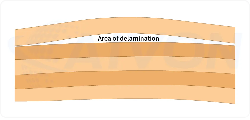
Delamination after flex testing or thermal stress can originate in incomplete cure, residual stress, or an adhesive chemistry that simply cannot survive the required environment. Matching the adhesive type to the application and verifying the full thermal profile prevents most field failures.
Poor peel strength
Poor peel strength or adhesive residue often points to material that has exceeded shelf life, improper storage, or incomplete surface preparation. The FPC surface finish and cleanliness should also be checked, as an unsuitable or contaminated surface can affect adhesion between the conductive layer and adjacent materials.
Recommended Process Control Checklist
|
Process Stage |
Key Inspection Item |
|---|---|
|
Incoming Material Inspection |
Verify thickness, appearance, and shelf life. |
|
Surface Preparation |
Ensure the FPC surface is clean and free of contamination. |
|
Lamination Process |
Control temperature, pressure, and dwell time within qualified process windows. |
|
Post-Lamination Inspection |
Check for bubbles, wrinkles, voids, and alignment accuracy. |
|
Reliability Verification |
Perform periodic peel-strength testing and process audits. |
FPC Coverlay Manufacturing Insights from Real Production Experience
In high-volume flexible-circuit factories, the coverlay sequence is an important part of the overall flexible PCB manufacturing process and typically runs as follows: incoming inspection and baking of the material, laser or die windowing under controlled conditions, clean-room alignment to the etched panels, lamination, optional post-bake, followed by AOI and electrical testing.
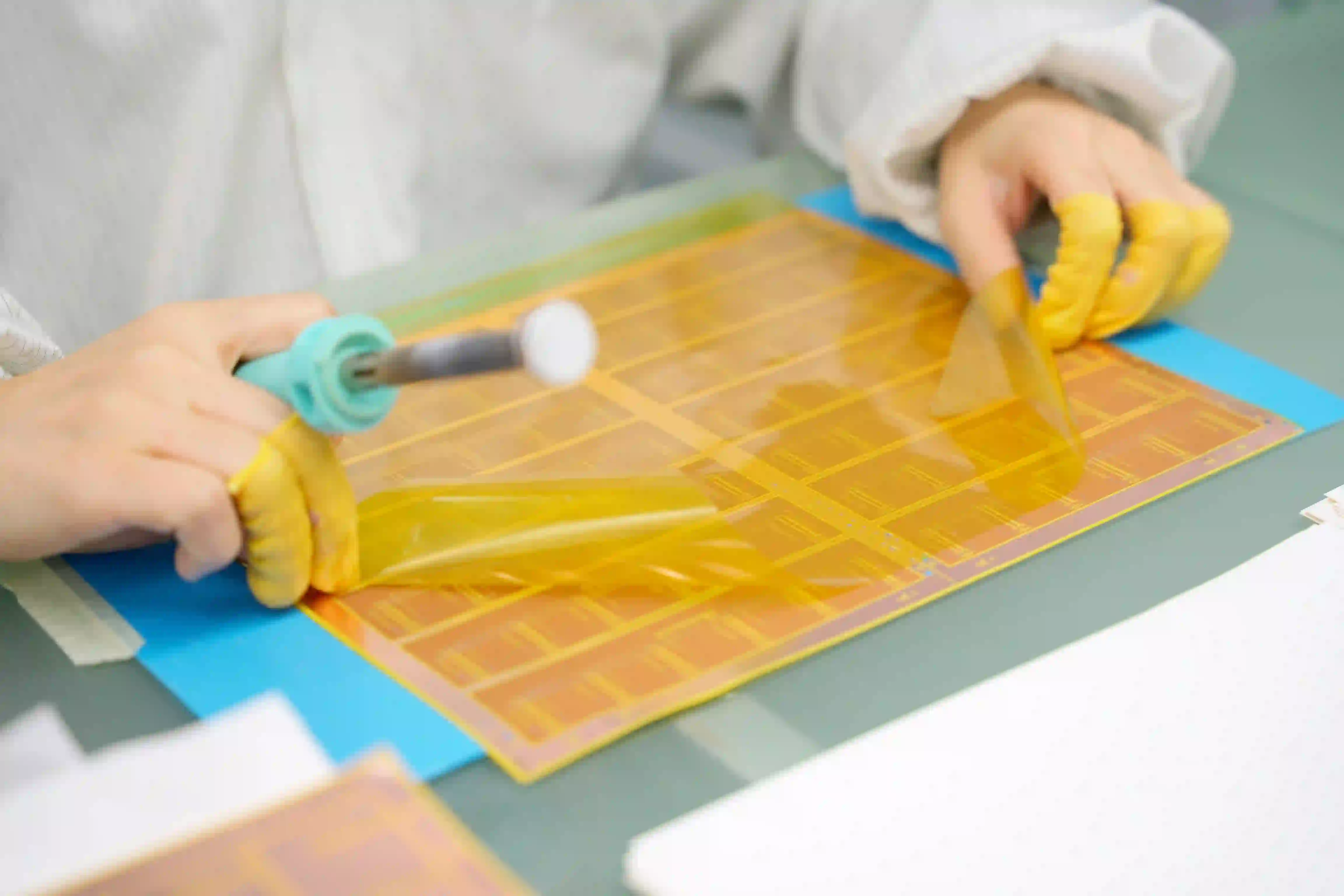
The same sequence appears whether the product is a simple single-sided antenna circuit or a multi-layer rigid-flex medical device; only the process parameters and inspection intensity change.
Two engineering trade-offs appear repeatedly. First is the balance between adhesive flow sufficient to encapsulate copper features and the risk of pad contamination. Acrylic systems give more flow and therefore more margin against incomplete encapsulation, but they demand tighter control of pressure and window sizing. Second is the decision to accept lower throughput with vacuum lamination on complex double-sided boards in order to eliminate chronic void problems that would otherwise appear in reliability testing.
Real production experience shows:
● Switching from acrylic to epoxy (or vice versa) has resolved recurring field delamination when the root cause was mismatched temperature capability.
● Moving a chronic void problem on multi-layer flex from roll-to-roll to vacuum lamination eliminated the defect without changing the material.
In both cases, the solution came from matching material behavior and process capability to the actual stresses the circuit would see, but not from simply specifying a "better" coverlay.
Conclusion: Selecting the Right FPC Coverlay
Choosing the right coverlay requires balancing flexibility, temperature resistance, chemical durability, and manufacturing feasibility. Acrylic and epoxy adhesive systems each have their strengths, but successful FPC production depends equally on precise lamination, accurate windowing, and process control.
By considering material selection together with manufacturing requirements, engineers can avoid common coverlay failures and build more reliable flexible circuits. The right FPC coverlay is determined by the balance between flex performance, temperature requirements, pad design, and manufacturing capability. Acrylic systems remain the preferred choice for dynamic bending, while epoxy systems provide additional thermal and chemical resistance.
For complex FPC designs, early review of coverlay material, window structure, and lamination process with the manufacturer can prevent costly redesigns and improve production yield.
FAQ
Q1: What is the difference between coverlay and soldermask in flex PCB design?
A1: Coverlay is a laminated polyimide film with adhesive, while solder mask (LPI) is a liquid coating that is cured after application. Coverlay provides better mechanical protection and flex life, making it the preferred choice for dynamic and high-reliability circuits. LPI is thinner and better suited for fine features on static or low-flex designs.
Q2: How should I size coverlay openings for reliable assembly?
A2: Make the opening larger than the pad, typically by adding 0.1–0.15 mm per side, to allow for adhesive flow and registration tolerance. Openings that are too small risk adhesive contamination on the pad, while oversized openings leave unprotected copper exposed. Always confirm the exact design rule with your fabricator.
Q3: What registration tolerance is realistic for laser-cut coverlay windows?
A3: Under controlled production conditions, laser-cut coverlay windows typically achieve registration accuracy of ±50–75 µm relative to the copper pads. Mechanical die cutting is generally less precise. Designers should provide sufficient annular ring and reliable fiducials to stay within the fabricator's demonstrated capability.
Q4: How long is the shelf life of acrylic vs epoxy coverlay, and how should it be stored?
A4: Acrylic systems generally offer a longer and more forgiving shelf life. Epoxy systems have a shorter shelf life and are more sensitive to temperature and humidity. Both materials should be stored in their original packaging under the manufacturer's recommended dry, temperature-controlled conditions, as expired material is a common cause of adhesion failures.
Q5: Can acrylic and epoxy coverlays be mixed on the same rigid-flex board?
A5: It is possible but rarely recommended. Different flow characteristics, curing behavior, and thermal expansion can create process-control challenges and residual stress at transition zones. Most fabricators prefer using a single adhesive chemistry unless there is a clearly validated performance reason to combine both.
Q6: Can FPC coverlay be used for high-density flexible PCB designs?
A6: FPC coverlay can be used in high-density flexible PCB designs, but the opening geometry, registration tolerance, adhesive flow, and pad spacing must be reviewed carefully. Fine-pitch pads may require specific coverlay processing capabilities to maintain reliable soldering and electrical connections.
Q7: Does FPC coverlay affect signal integrity?
A7: FPC coverlay can affect the electrical environment of a flexible circuit because its dielectric properties and thickness contribute to the overall circuit construction. For high-speed or impedance-controlled designs, coverlay should be considered together with the substrate, copper geometry, and stack-up during design review.
Q8: How can I reduce FPC coverlay manufacturing costs?
A8: Cost can be influenced by material selection, opening complexity, production volume, tooling requirements, and processing methods. Simplifying unnecessary opening patterns, reviewing the coverlay construction early, and selecting a material compatible with the intended manufacturing process may help reduce production costs.
Q9: What information should I provide when ordering FPC coverlay?
A9: Useful information includes the FPC design files, material requirements, copper thickness, coverlay film and adhesive specifications, opening geometry, bend requirements, operating environment, and expected production volume. Providing these details helps the manufacturer review material compatibility and manufacturing feasibility.
Q10: Is FPC coverlay suitable for both prototype and mass production?
A10: FPC coverlay can be used in both prototype and mass-production flexible PCB projects. The suitable processing method depends on the design, material, opening geometry, and production requirements. Early review of the coverlay construction can help ensure that the prototype design is suitable for later production.