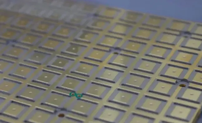
The four surface finishes most commonly used on flexible printed circuits (FPC) are ENIG, OSP, hard gold, and immersion silver. ENIG remains the most common choice for fine-pitch SMT on flexible circuits, yet the nickel underlayer must stay out of high-cycle bend areas or be tightly controlled. OSP adds almost no stiffness and costs the least, but its shelf life and reflow window are limited. Hard gold belongs on contact fingers that see repeated mating. Immersion silver offers good solderability at lower cost than ENIG when tarnish can be managed.
Unlike rigid boards, these finishes must also survive repeated bending, thinner copper, and polyimide substrate movement. Choosing the wrong one often leads to cracking in the bend zone, loss of solderability, or unnecessary cost.
Highlights
● ENIG provides the best solderability for fine-pitch flexible PCB assembly.
● OSP offers the lowest cost and highest flexibility for dynamic bend applications.
● Hard gold should only be used on connector fingers outside the bend region.
In this guide you will see how the four finishes actually perform on polyimide constructions, where each one fails in practice, what thickness and placement rules experienced fabricators follow, and a clear decision framework you can apply to the next design.
Why FPC Surface Finish Selection Matters
An FPC surface finish protects exposed copper from oxidation while supporting soldering, electrical contact, and long-term reliability. However, selecting a finish for a flexible circuit requires more consideration than simply choosing a coating that works well on a rigid PCB.
The flexible PCB circuit can experience bending, folding, vibration, and repeated mechanical movement during operation. These conditions can affect plated areas, especially when a surface finish is located close to an active bend zone. The finish must therefore be compatible with both the electrical function of the exposed copper and the mechanical requirements of the FPC.
For rigid-flex PCBs, the requirements can vary between rigid and flexible sections. SMT pads on a rigid section may prioritize solderability and surface flatness, while connector contacts may require a more wear-resistant finish. A flex section that undergoes repeated bending may have different requirements again.
For these reasons, FPC surface finish selection should be considered together with the circuit structure, assembly method, bend requirements, and intended application.
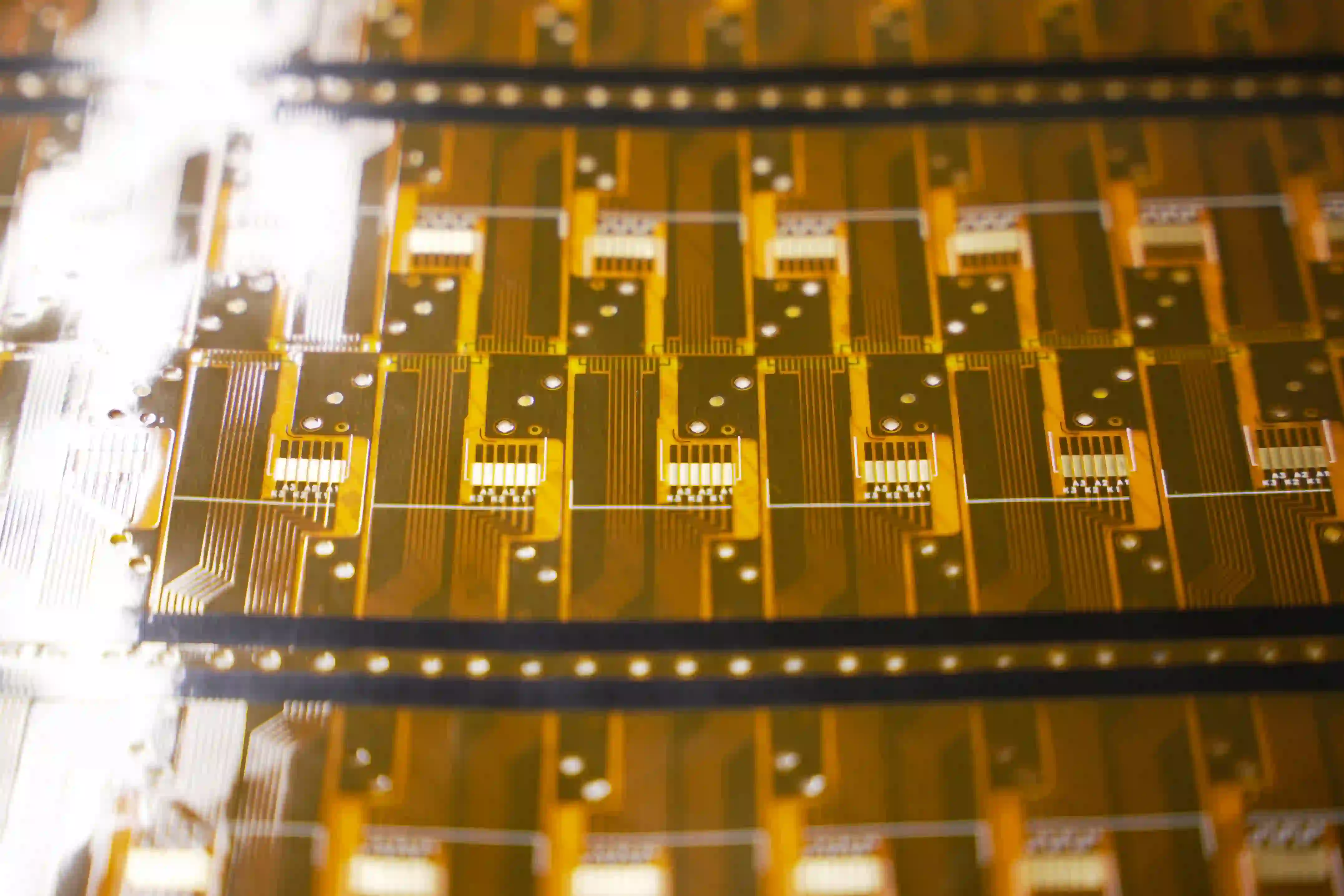
Polyimide stretches and recovers. Copper foil, especially rolled-annealed foil used for dynamic flex, can tolerate repeated strain. Nickel, however, is far less ductile. When an electroless nickel layer sits across a bend line, cyclic tension and compression open micro-cracks. Those cracks propagate into the copper and eventually open the conductor. The same mechanical mismatch appears with thick electrolytic hard gold over nickel. OSP and immersion silver avoid the nickel problem, yet each brings its own limitations in shelf life, tarnish, or reflow tolerance.
Failure modes unique to flexible circuits therefore center on the bend region: nickel cracking, adhesion loss at the copper–finish interface under cyclic strain, and accelerated oxidation of thin or porous coatings when the coverlay edge leaves copper exposed to moisture or contaminants. Because rework on an assembled flex module is expensive and sometimes impossible, the finish decision directly affects first-pass yield and field returns.
Types of FPC Surface Finish
Four finishes dominate production flexible circuits today. Each has a clear process, typical thickness range when applied to FPC, and a practical performance envelope.
ENIG (Electroless Nickel Immersion Gold)
ENIG deposits 3–6 µm of electroless nickel followed by 0.05–0.10 µm of immersion gold. The nickel acts as a diffusion barrier and the gold protects it from oxidation until soldering. The surface is flat, ideal for fine-pitch SMT and aluminum wire bonding, though designers must evaluate
OSP (Organic Solderability Preservative)
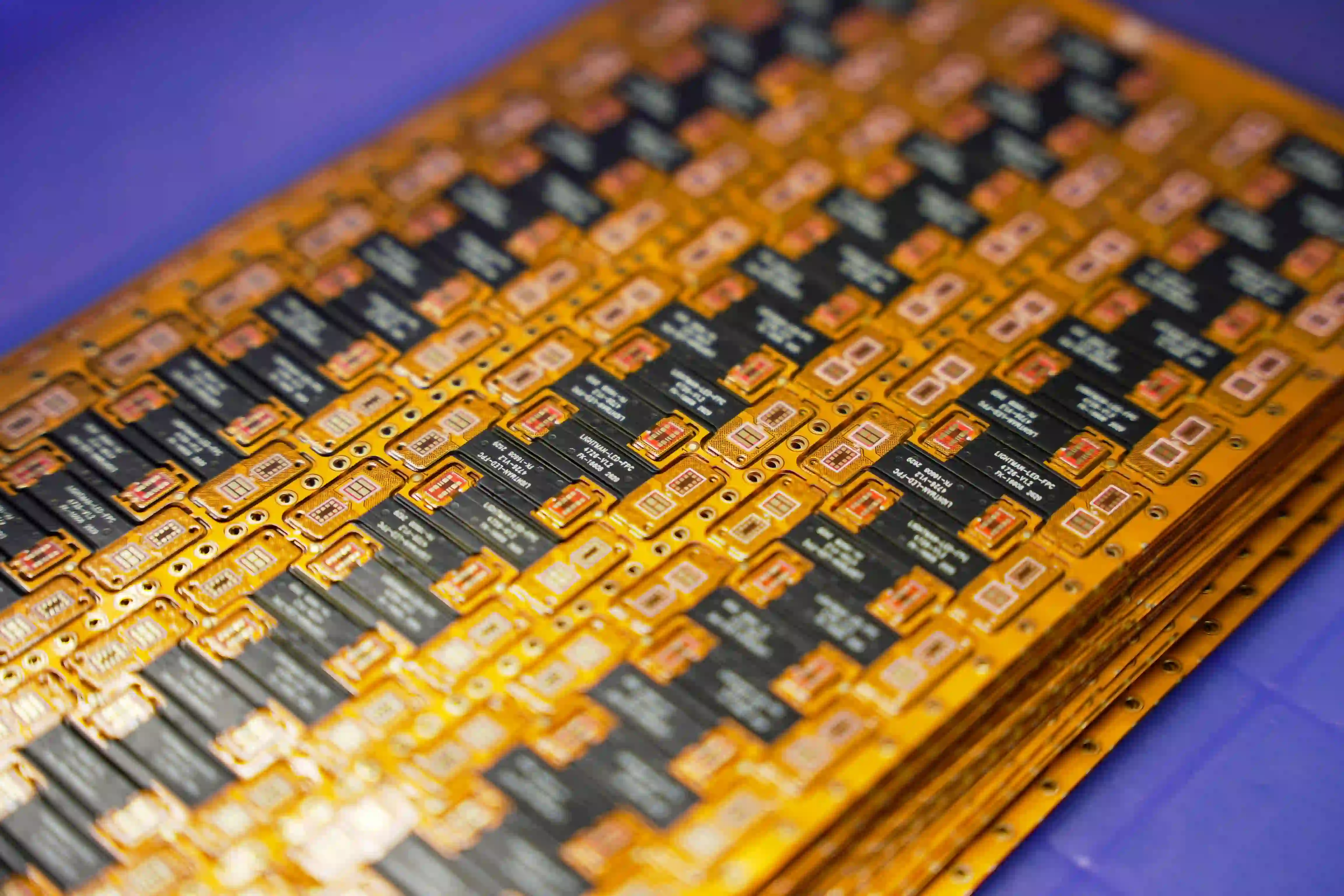
OSP applies a thin azole-based organic film, typically 0.2–0.5 µm, that bonds to clean copper and prevents oxidation until flux removes it during reflow. It adds almost no stiffness, costs the least, and leaves the copper fully flexible. The trade-offs are a practical shelf life of 3–6 months, sensitivity to handling and multiple reflow cycles, and unsuitability for wire bonding or long-term exposed contacts. OSP remains the preferred finish for high-volume consumer flex circuits that move quickly from fabrication to assembly and see only static or low-cycle bending.
Hard Gold (Electrolytic Hard Gold)
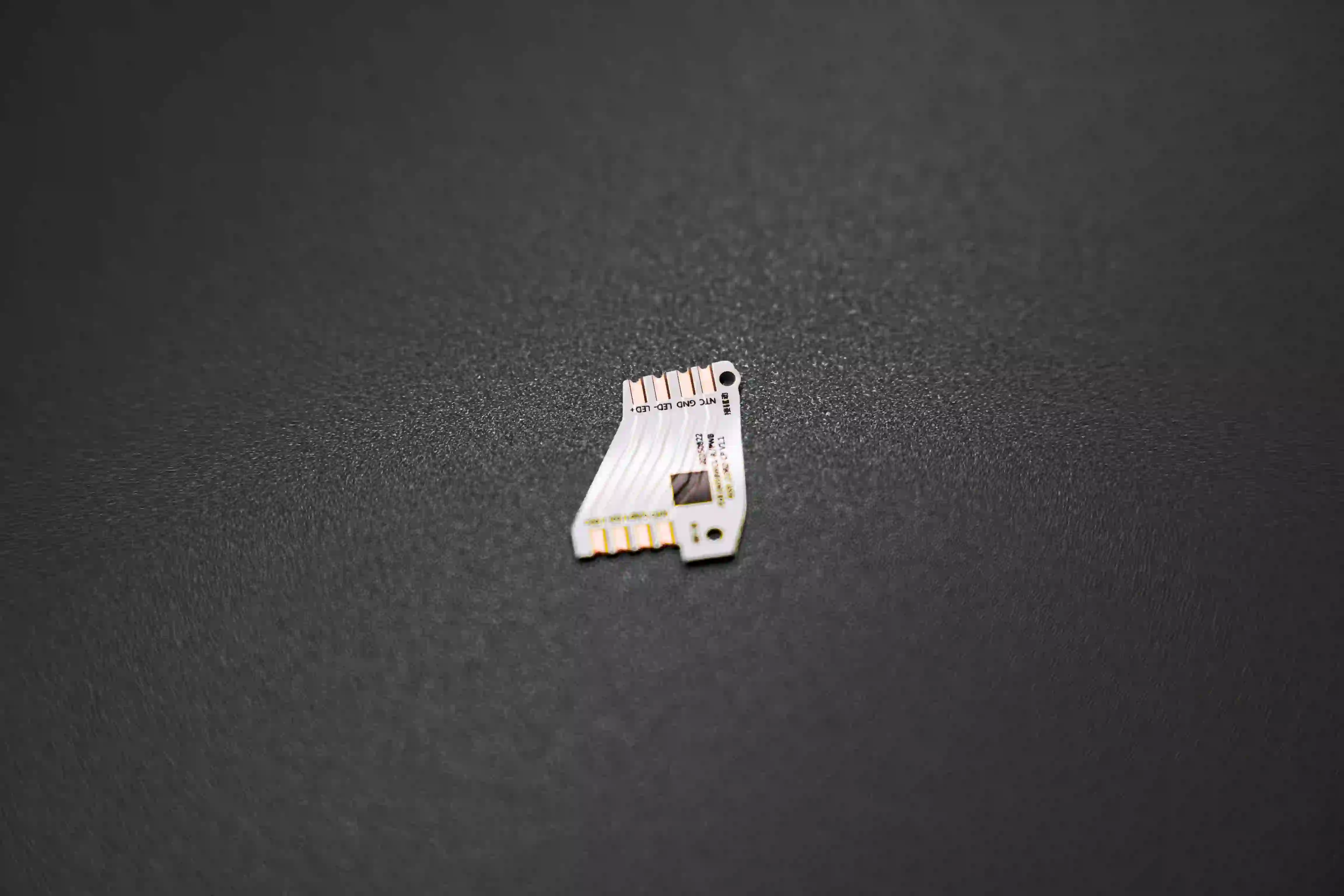
Hard Gold is electroplated gold alloy (usually cobalt-hardened) over a nickel underplate. Typical thickness on FPC contact fingers is 0.5–1.5 µm gold over 2.5–5 µm nickel, selected according to expected mating cycles. The finish delivers high hardness, low contact resistance, and excellent wear resistance for ZIF connectors, edge fingers, and sliding contacts. Because both the gold and the nickel add local stiffness, the plated zone must sit outside the bend region and is normally backed by a stiffener. Selective plating with tape or dry-film masking is required so that solderable areas retain a different finish.
Immersion Silver
Immersion silver deposits a pure silver layer of roughly 0.1–0.4 µm directly on copper by galvanic displacement. It offers excellent solderability, a flat surface, and lower cost than ENIG. Silver's high conductivity also benefits some RF flex designs. The main risks are tarnish in humid or sulfur-containing environments and the possibility of silver migration under bias and moisture. Packaging must be sealed and sulfur-free; assembly should occur within the practical shelf life of 6–12 months when properly stored. Immersion silver sees less use on dynamic flex than on rigid boards, but it remains viable when nickel must be avoided and cost is a concern.
Main FPC Surface Finish Property Comparison
|
Finish |
Typical Thickness on FPC |
Solderability |
Bend Durability |
Practical Shelf Life |
Relative Cost |
Best FPC Use Cases |
|---|---|---|---|---|---|---|
|
ENIG |
Ni 3–6 µm + Au 0.05–0.10 µm |
Excellent |
Limited in dynamic zones |
6–12 months |
Medium |
Fine-pitch SMT, general purpose |
|
OSP |
0.2–0.5 µm organic |
Good |
Excellent |
3–6 months |
Lowest |
High-volume consumer, static flex |
|
Hard Gold |
Au 0.5–1.5 µm over Ni |
Connector contacts only |
Poor in bend zones |
12+ months |
Highest |
ZIF fingers, wear contacts |
|
Immersion Silver |
0.1–0.4 µm Ag |
Excellent |
Good |
6–12 months |
Low–Medium |
Cost-sensitive SMT, some RF |
FPC Surface Finish for Flexible and Rigid-Flex PCBs
On a rigid board the copper and laminate stay essentially static after assembly. Thickness targets, process windows, and reliability tests were developed for that environment. Flexible circuits change the rules in four practical ways.
First, mechanical stress is continuous or intermittent. A finish that survives 1 000 thermal cycles on FR-4 can still crack after 10 000 bend cycles on polyimide. Nickel-bearing finishes therefore require explicit keep-out distances from the bend line.
Second, the substrate and copper are thinner and more compliant. Adhesion of some finishes to polyimide constructions is lower, and coverlay openings can leave abrupt thickness transitions that concentrate strain. Rolled-annealed copper helps, but the finish still has to match the copper's ductility.
Third, the process window is tighter. Flexible panels warp more easily during plating and drying. Current density, rinse quality, and drying temperature must be controlled more carefully to avoid non-uniform deposits or residual stress.
Selective hard-gold plating on thin copper also risks distortion if the plating current is not well managed.
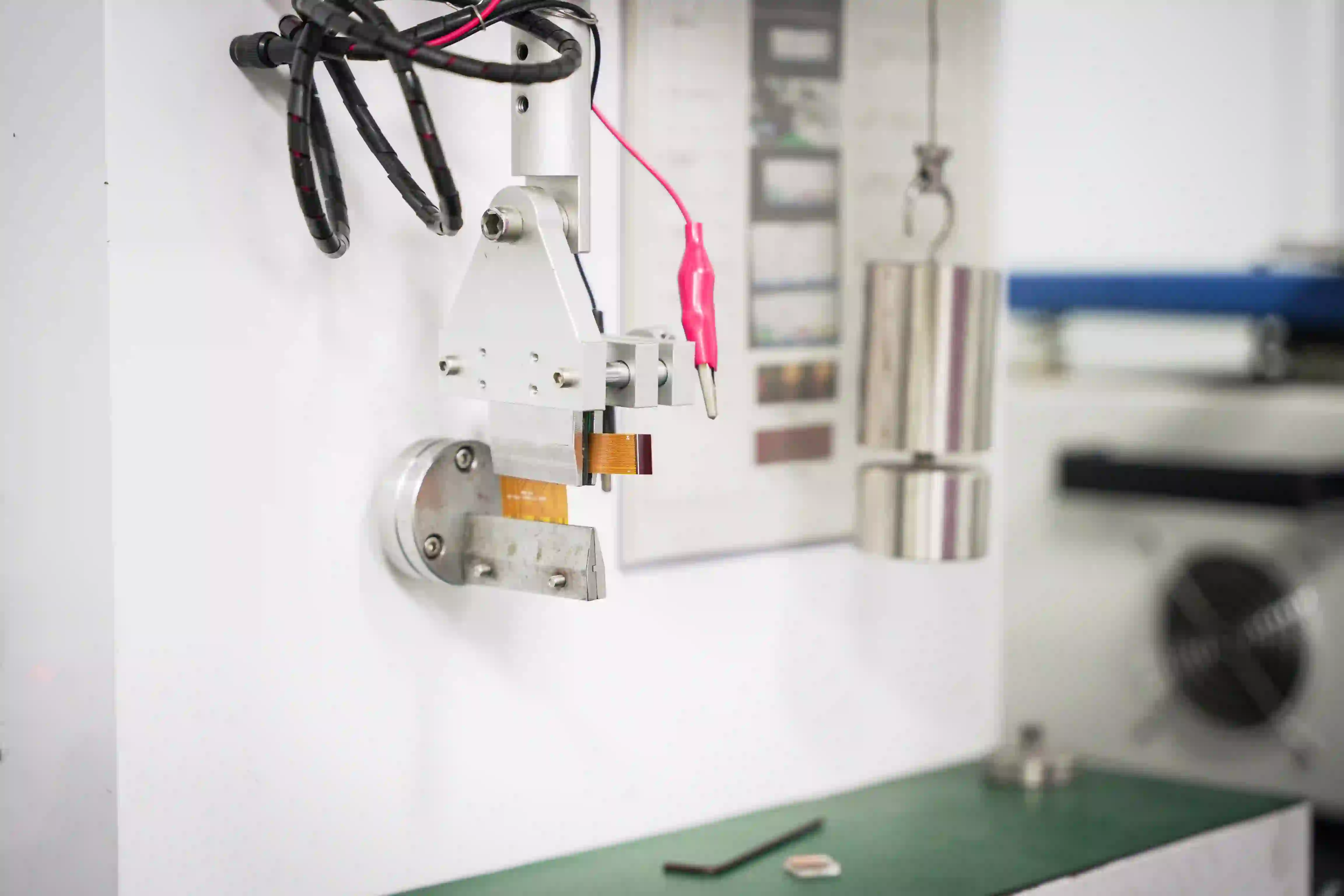
Fourth, reliability qualification must include dynamic flex testing after the finish is applied. Thermal cycling alone is insufficient. Fabricators who regularly process FPC therefore measure nickel thickness in the bend zone by cross-section, perform tape adhesion tests after flexing, and run solderability checks after simulated aging.
Design rules change accordingly. Pad sizes and annular rings may need to be larger when a thicker finish is used. FPC coverlay overlap and stiffener placement must keep finish transitions away from the highest strain region. These adjustments are routine once the mechanical environment is understood.
FPC Surface Finish Design Rules for Bend Areas
The bend zone is the highest-risk area because cyclic tensile and compressive strain concentrates at the copper–finish interface. The practical rules that experienced manufacturers follow are straightforward.
For dynamic flex applications, keep all nickel-bearing finishes outside the moving arc. If an ENIG pad must approach the bend, specify the lowest practical nickel thickness and a ductile nickel chemistry, then verify with flex testing. OSP and immersion silver can enter the bend zone more freely because they add negligible stiffness.
For static or one-time fold applications the restrictions relax. ENIG with controlled thickness is commonly accepted provided the bend radius is adequate.
Flexible PCB design rules that reduce risk include:
● Maintain a minimum distance between the edge of a plated feature and the bend line, which is often 1 mm or more, depending on radius and copper weight.
● Ensure coverlay overlap is consistent so that finish thickness does not change abruptly.
● Use selective plating for hard gold so the plated golds should stop well before the flex region and are supported by a stiffener.
● Avoid abrupt copper or finish thickness steps that act as stress risers.
Common Field Failures:
|
Common Field Failure |
Root Cause |
Impact |
|---|---|---|
|
Nickel cracks propagating into copper |
Plating placement or thickness not optimized for repeated bending conditions |
Cracks extend into the copper layer, causing electrical failure |
|
Silver migration under bias |
Surface finish selection or design not considering environmental stress and electrical bias conditions |
Insulation degradation and potential short circuits |
|
OSP breakdown after multiple reflows |
Surface finish thickness or process selection unsuitable for repeated thermal cycles |
Reduced solderability and connection reliability |
How to Select the Best Surface Finish for Your Flexible PCB
Rank the decision criteria in the order most engineering teams actually use them.
1. Mechanical requirement: dynamic flex cycles, minimum bend radius, or simple static fold.
2. Interconnection method: reflow soldering, wire bonding, ZIF or edge-connector mating, press-fit.
3. Environmental exposure: humidity, sulfur, temperature cycling, chemical cleaning.
4. Assembly process constraints: number of reflow cycles, required shelf life before assembly.
5. Cost and volume targets.
Application-based guidance follows directly from those priorities:
- High-cycle dynamic flex, like wearables, medical probes, robotics: prefer OSP or immersion silver in the bend zone; keep ENIG and hard gold outside it.
- Fine-pitch SMT with multiple reflows and moderate flex: ENIG with controlled nickel thickness and pads kept clear of the active bend.
- ZIF or edge connectors requiring repeated insertion: selective hard gold on the fingers only, backed by a stiffener.
- High-volume consumer modules with fast assembly: OSP.
- Cost-sensitive designs that still need good solderability and some shelf life: immersion silver, provided packaging and storage are controlled.
- Wire bonding: ENIG (aluminum) or soft electrolytic gold; OSP and immersion silver are unsuitable.
Cost of ownership matters more than piece price. A cheaper OSP board that oxidizes in inventory or fails after two reflows can cost more than an ENIG board that yields consistently. Experienced fabricators therefore ask for the bend-cycle target, the number of reflows, and the expected storage time before they lock the finish specification.
Manufacturing Considerations for FPC Surface Finishes
In flexible PCB manufacturing, the most common points that determine success with FPC surface finishes are thickness control, placement relative to the bend zone, and handling after plating.
For ENIG, nickel thickness is normally held toward the lower end of the 3–6 µm range on flexible circuits to reduce the risk of cracking. Gold stays thin (0.05–0.10 µm). Hard gold is applied selectively only to contact fingers and must stop well before any bend area. OSP and immersion silver require careful packaging because of their shorter shelf life and sensitivity to oxidation or tarnish.
Flexible panels warp more easily than rigid boards, so rinse quality, drying temperature, and bath uniformity need tighter monitoring to avoid uneven deposits or residual stress.
At AIVON, the large majority of flexible circuits are finished with immersion gold (ENIG). This remains the default choice for most customers because it delivers reliable solderability, acceptable shelf life, and consistent results on polyimide constructions.
Conclusion
Choosing an FPC surface finish is ultimately a mechanical and process decision as much as a metallurgical one. Match the finish to the bend environment first, then to the interconnection method and assembly constraints. When those priorities are clear, the selection among ENIG, OSP, hard gold, and immersion silver becomes straightforward and the risk of field failures drops sharply.
FAQs
Q1: Is ENIG suitable for high-cycle dynamic flex FPCs, and what nickel thickness is recommended?
A1: ENIG can be used on flexible circuits, but the nickel layer should be kept outside the active bend zone in high-cycle applications whenever possible. If this cannot be avoided, nickel thickness should remain toward the lower end of the typical 3–6 µm range (commonly 3–5 µm), and a more ductile nickel formulation is recommended. Always validate the final design with dynamic flex testing on the actual stack-up.
Q2: How does OSP performance on FPC compare with rigid boards regarding shelf life and multiple reflows?
A2: OSP performs similarly on flexible and rigid PCBs. Under proper sealed packaging, its practical shelf life is typically 3–6 months, and it generally supports two to three reliable reflow cycles. On FPCs, OSP offers the additional benefit of adding virtually no stiffness, making it a popular choice for high-volume flexible assemblies.
Q3: Can hard gold be applied selectively so that only connector fingers receive the thick gold while the bend area remains thinner?
A3: Yes. Selective electrolytic hard gold plating is standard practice. Connector fingers are selectively plated using masking or bus-bar techniques, while the remainder of the circuit receives ENIG, OSP, or another solderable finish. The hard-gold region should terminate before the bend area and is typically reinforced with a stiffener.
Q4: What causes immersion silver to tarnish on FPC and how can it be mitigated in storage and assembly?
A4: Immersion silver tarnishes through reactions with sulfur compounds and moisture in the air. The risk can be minimized by using sulfur-free sealed packaging, maintaining controlled storage humidity, reducing handling time, and assembling the boards within their recommended shelf life. Once soldered or protected with a conformal coating, the risk of tarnishing decreases significantly.
Q5: How long does ENIG last?
A5: Under proper sealed packaging, ENIG typically maintains good solderability for 6–12 months. After assembly, when the gold surface is covered by solder, the long-term reliability depends primarily on the solder joints and the overall product design rather than the surface finish itself.
Q6: Which surface finish costs the least?
A6: OSP is generally the lowest-cost surface finish for FPCs. It uses a thin organic protective coating instead of precious metals, making it significantly more economical than ENIG, immersion silver, or hard gold while still providing good solderability for many applications.
Q7: What should be shown on an FPC fabrication drawing for surface finish?
A7: An FPC fabrication drawing should clearly identify the required surface finish for each applicable area and distinguish it from other board specifications. Depending on the design, the documentation may also need to define finish thickness, plating areas, exposed-pad locations, and any finish-specific notes. Clear drawing requirements help the fabricator interpret the intended finish consistently during production.
Q8: Can an FPC surface finish be changed after the PCB design is released?
A8: A surface finish change should be reviewed as a manufacturing change rather than treated as a simple material substitution. The replacement finish may affect soldering, contact performance, mechanical behavior, appearance, and compatibility with the existing fabrication process. The PCB manufacturer should review the change against the original drawings and assembly requirements before production.
Q9: How is FPC surface finish quality inspected during manufacturing?
A9: Inspection can include visual examination of the finished surface, verification of plating coverage, dimensional checks, and process-specific testing where required. For production applications with tighter requirements, the manufacturer may also monitor finish thickness and other relevant process parameters. The inspection method should be based on the selected finish, application, and applicable manufacturing specifications.
Q10: Can the same FPC surface finish specification be used for prototype and mass production?
A10: The same basic finish can often be specified for both prototype and mass production, but the manufacturing process may differ between production stages. Prototype quantities may use different panelization, processing, or material sourcing conditions. Before scaling production, the manufacturer should confirm that the selected finish and its process controls remain consistent with the approved design and assembly requirements.
Q11: Does FPC surface finish need to comply with specific industry standards?
A11: The required standards depend on the application, customer requirements, and manufacturing specification. General PCB fabrication standards may define requirements for surface finish quality, while automotive, medical, aerospace, or other specialized applications may impose additional requirements. The applicable standard should be identified in the project documentation rather than assumed from the finish type alone.