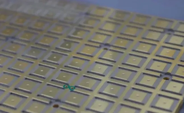
Flexible PCB manufacturing plays an important role in modern electronic systems where traditional rigid PCBs cannot provide the required flexibility, compactness, or three-dimensional routing. Flexible printed circuits are widely used in automotive electronics, medical devices, aerospace systems, wearable products, and consumer electronics.
Successful flex PCB fabrication depends on more than the circuit layout. Substrate selection, copper foil type, coverlay, adhesive systems, surface finish, and manufacturing controls all affect the final performance of an FPC. These factors influence flexibility, thermal stability, signal integrity, environmental resistance, and long-term reliability.
This guide explains the key FPC materials, manufacturing processes, common failure modes, and material selection considerations for different applications. It also outlines how engineers can evaluate flexible circuit designs and work with an experienced manufacturer to achieve consistent production results.
Understanding Flexible Printed Circuits and the Critical Role of Materials
What Is an FPC?
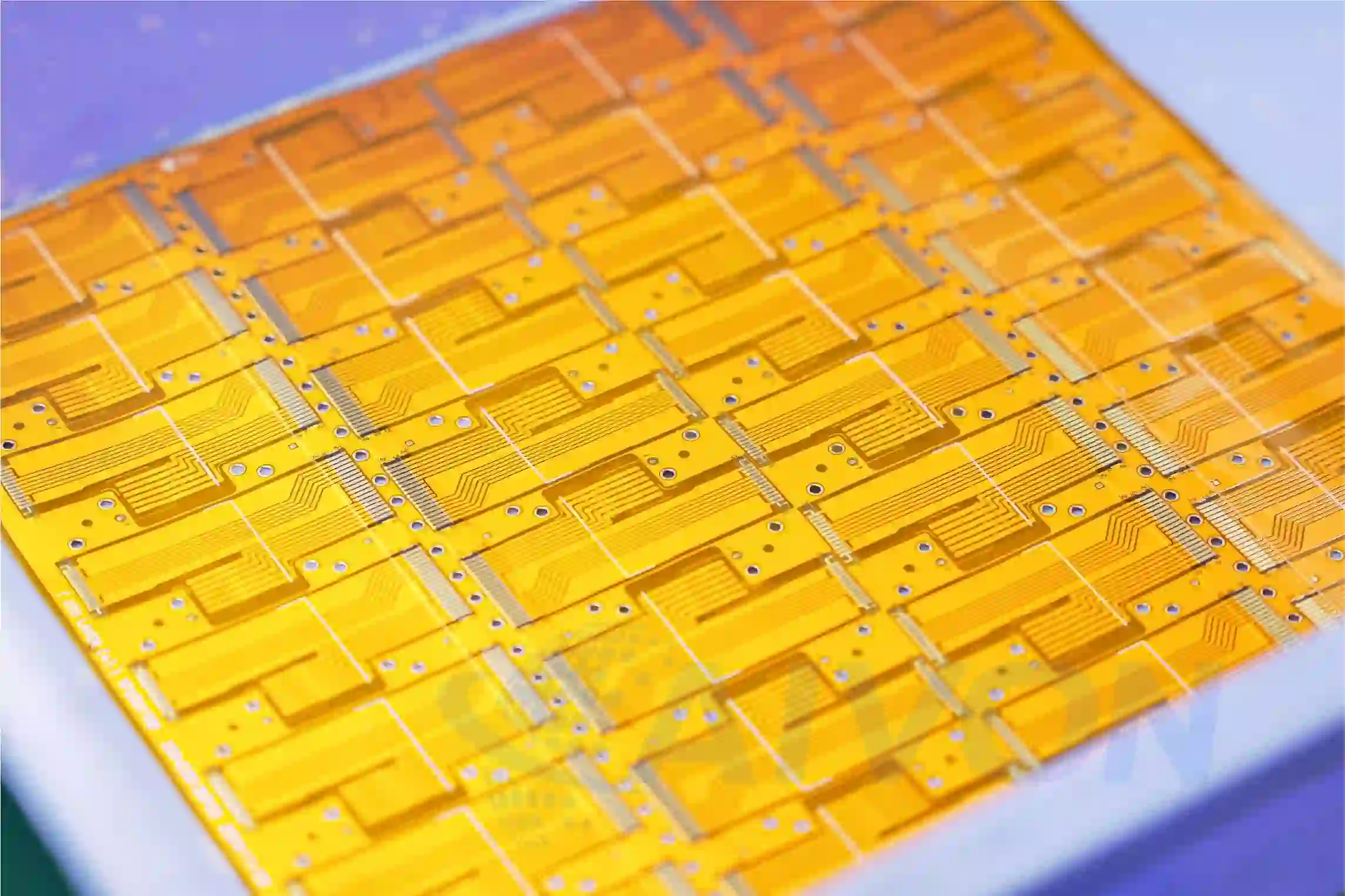
FPC stands for Flexible Printed Circuit. It is a printed circuit board built on a flexible substrate instead of a rigid material. This structure allows the circuit to bend, fold, or fit into compact spaces while maintaining electrical connections between components.
FPCs are commonly used where space, weight, and mechanical flexibility are important. Typical applications include displays, cameras, battery connections, medical devices, automotive electronics, wearable products, and industrial equipment.
Material choices influence nearly every key performance metric:
● Mechanical flexibility and fatigue life: Determines how many bend cycles the circuit can endure.
● Thermal performance: Affects solderability, operating temperature range, and resistance to reflow processes.
● Electrical characteristics: Impacts impedance control, signal loss, and high-frequency performance.
● Environmental resistance: Influences moisture absorption, chemical compatibility, and outgassing behavior.
● Manufacturing yield and cost: Directly affects production economics and scalability.
In high-reliability sectors such as automotive (under-hood electronics), medical (implantable or reusable devices), and aerospace (vibration-intensive environments), suboptimal material selection often leads to field failures that carry substantial warranty and safety implications.
How Are Flexible PCBs Different from Rigid PCBs?
The main difference is the substrate and the mechanical behavior of the finished board.
Rigid PCBs usually use materials such as FR-4, which provide a stable and solid structure. Flexible PCBs use materials such as polyimide or polyester, allowing the circuit to bend and conform to the product structure.
Compared with rigid PCBs, flexible circuits can offer:
-
Better space utilization
-
Lower assembly weight
-
Fewer connectors and solder joints
-
Easier three-dimensional routing
-
Better suitability for moving or bending applications
However, flexible circuits require careful control of bend areas, copper layout, coverlay design, and material selection during flexible PCB manufacturing.
Key Materials Used in Flexible PCB Manufacturing
Polyimide and Other Flexible Substrate Materials
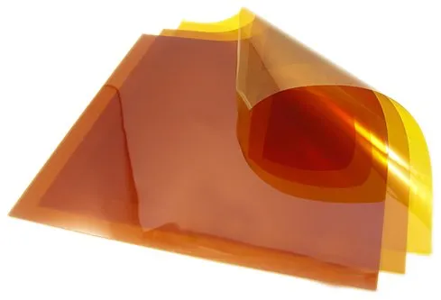
Polyimide (PI) films represent the gold standard for demanding FPC applications. These aromatic polymers offer exceptional thermal stability with continuous service temperatures reaching 260°C and short-term tolerance exceeding 300°C during lead-free soldering. Their low coefficient of thermal expansion closely matches copper, minimizing stress during thermal cycling.
PI films exhibit excellent tensile strength, high elongation before break, and superior dielectric properties. When properly engineered, PI-based FPCs can achieve dynamic flex life exceeding one million cycles. Major commercial grades such as DuPont Kapton or Kaneka Apical provide consistent performance across global supply chains.
Polyester and Other Cost-Effective Substrate Options
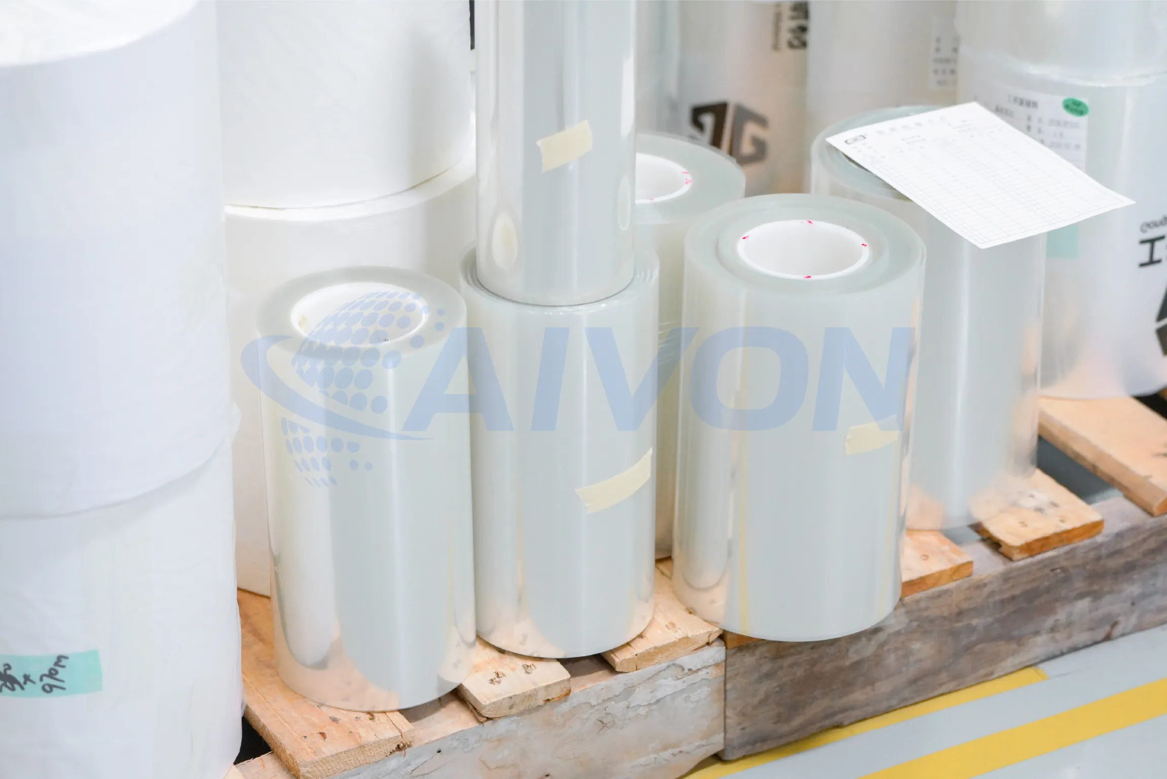
Polyester (PET) films serve as a cost-effective option for less demanding applications. PET offers good electrical insulation and mechanical flexibility at significantly lower material costs — often 30-50% cheaper than PI. However, its limitations are notable: maximum continuous operating temperature usually ranges from 85°C to 150°C depending on grade, higher moisture absorption, and reduced long-term thermal stability. PET suits static flex-to-install designs in consumer electronics, such as display connections in smartphones or laptops, where extreme temperatures or dynamic motion are absent.
Advanced polymer options fill specific performance gaps:
● Polyethylene Naphthalate (PEN): Provides a middle ground with better thermal resistance than PET (up to 180°C) and improved dimensional stability.
● Liquid Crystal Polymer (LCP): Delivers ultra-low dielectric constant and dissipation factor, near-zero moisture absorption, and excellent high-frequency performance up to mmWave ranges. LCP excels in 5G antennas, radar modules, and high-speed data applications.
● PTFE (Polytetrafluoroethylene) composites: Offer superior chemical resistance and low dielectric loss for RF/microwave circuits, though they present unique processing challenges due to low surface energy.
Comparative Analysis of Substrate Materials
This table provides a comparison of common FPC base materials.
|
Property |
Polyimide (PI) |
Polyester (PET) |
LCP |
PEN |
|---|---|---|---|---|
|
Max Operating Temp (°C) |
260+ |
85-150 |
200+ |
150-180 |
|
Moisture Absorption (%) |
1.3-3.0 |
0.4-0.8 |
<0.02 |
0.2-0.4 |
|
CTE (ppm/°C) |
20-30 |
20-50 |
10-20 |
15-25 |
|
Flex Life (Dynamic) |
Excellent (>1M cycles) |
Moderate |
Good |
Good |
|
Dielectric Constant |
3.4-3.5 |
3.0-3.5 |
2.9-3.0 |
3.0-3.2 |
|
Relative Cost |
High |
Low |
Very High |
Medium |
|
Typical Applications |
Automotive, Aerospace, Medical |
Consumer Electronics |
RF/5G, High-Speed |
Industrial Sensors |
Engineers must evaluate these properties against specific application requirements rather than selecting based solely on cost.
Copper Foil Engineering: Rolled Annealed vs Electrodeposited
While substrate materials form the mechanical and thermal foundation of an FPC, conductor performance is equally critical. In many dynamic flex applications, the copper layer experiences the highest mechanical stress during bending cycles. As a result, selecting the appropriate copper foil structure is often just as important as choosing the right dielectric material. Copper foil selection represents one of the most critical decisions in dynamic FPC design. Two primary types dominate the industry:
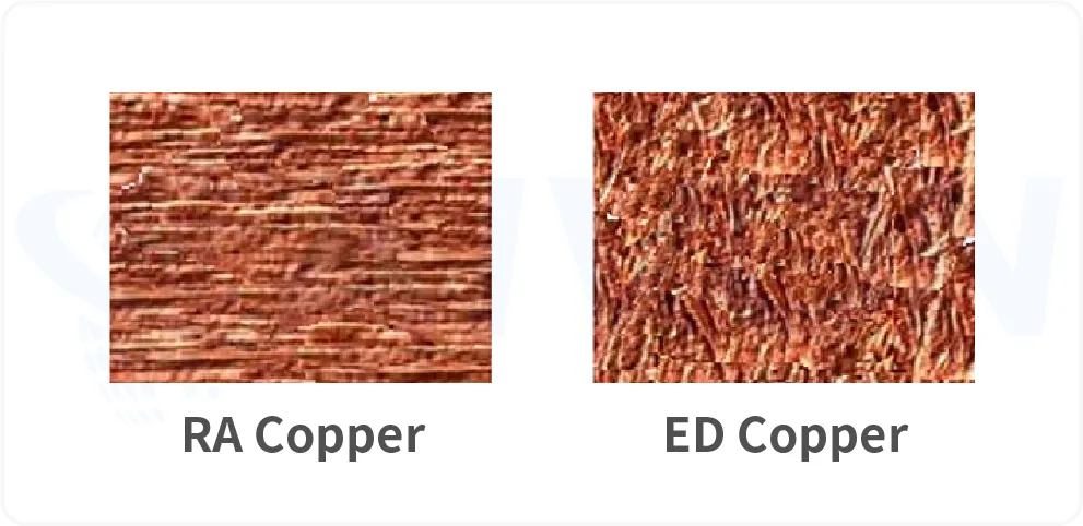
Rolled Annealed (RA) Copper undergoes a mechanical rolling and annealing process that creates a smooth, elongated grain structure. This microstructure provides superior ductility and resistance to fatigue cracking. When the rolling direction aligns parallel to the primary bend axis, RA copper delivers exceptional flex endurance. Typical thicknesses range from 9μm to 35μm for fine-line applications. RA copper is the preferred choice for applications requiring repeated dynamic flexing, such as hinge connections in foldable devices or automotive camera modules.
Electrodeposited (ED) Copper grows through electrochemical deposition, resulting in a more columnar grain structure with higher surface roughness on one side. This roughness improves adhesion to dielectrics but reduces ductility compared to RA. ED copper performs adequately in static flex or high-current applications and offers cost advantages, especially in thicker gauges (up to 70μm or more for power distribution).
Surface treatment and grain orientation significantly affect performance. Reverse treat (RT) or low-profile foils improve etchability and high-frequency characteristics by reducing skin effect losses.
Manufacturing and Material Selection Implications
Copper foil selection directly influences downstream FPC fabrication performance, especially in lamination, etching, and bending reliability.
● Dynamic flex reliability: RA copper's elongated grain structure improves resistance to micro-crack initiation during repeated flexing, making it more suitable for high-cycle bending structures.
● Lamination adhesion: ED copper's naturally rougher surface enhances bonding strength with dielectric materials, improving peel strength in multilayer constructions.
● Etching precision: Lower-profile treated foils (reverse treated or very low profile ED/RA) improve line definition and reduce undercutting, which is critical for fine-feature circuits.
● Thickness and process trade-offs: Thicker ED copper improves current carrying capacity but increases etch difficulty and minimum line/space limitations, requiring tighter process control.
However, conductor reliability depends on more than copper selection alone. Flexible circuits also require protective materials that shield traces from mechanical damage, moisture, and environmental contamination while preserving bendability. This role is fulfilled by the coverlay system.
How Coverlay Selection Affects FPC Protection and Flexibility
FPC Coverlay is the primary protective layer for flexible circuits, replacing the solder mask used on rigid PCBs. It consists of a thin polymer film (usually PI or PET) coated with adhesive, providing mechanical support, electrical insulation, and environmental protection against dust, moisture, and chemicals.
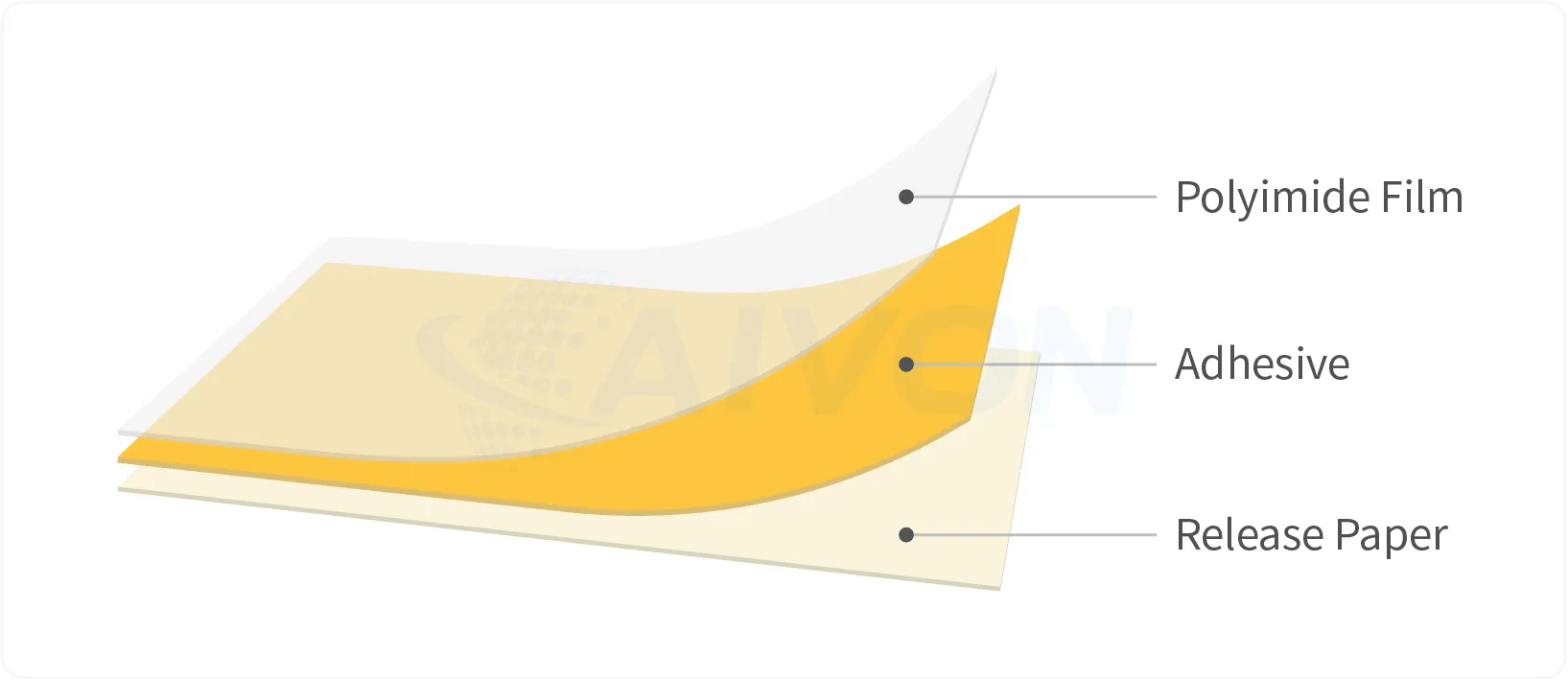
In production, coverlay thickness (typically 12.5μm, 25μm, or 50μm) creates important trade-offs. Thinner coverlays maximize flexibility and are preferred for tight bend radius applications, but they offer less abrasion resistance. Thicker coverlays improve durability and insulation reliability but can reduce overall circuit flexibility and increase stiffness in dynamic zones.
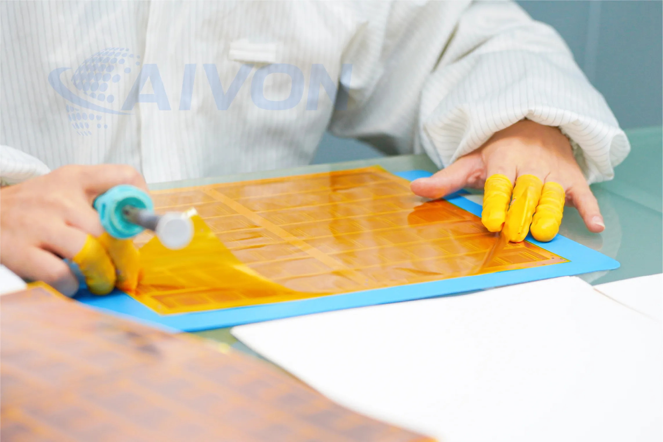
Material choice for coverlay should match the base substrate. PI coverlay paired with PI substrate provides the best thermal matching and long-term reliability in high-temperature or dynamic applications. PET coverlay is often used with PET substrates for cost-sensitive consumer products. The effectiveness of any coverlay system depends heavily on how it is bonded to the underlying circuit structure. Adhesive selection therefore becomes a key engineering consideration, influencing flexibility, thermal resistance, manufacturing yield, and long-term reliability.
Adhesive Systems in FPC Production: Acrylic vs Epoxy Selection
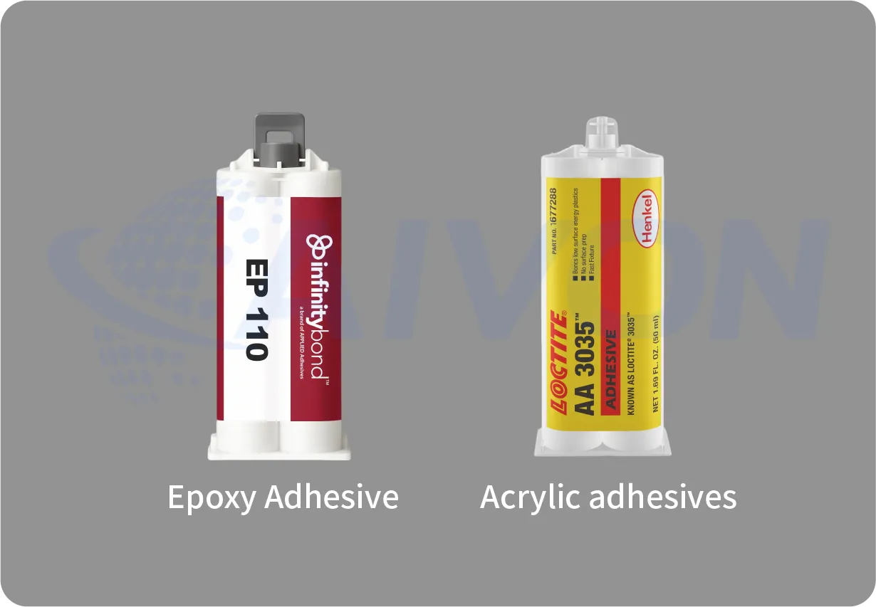
Adhesives serve as the bonding bridge between copper foil, substrate, and coverlay. They significantly influence manufacturing process windows, final mechanical properties, and long-term reliability.
Acrylic adhesives offer excellent flexibility and are widely used in dynamic FPC production. They maintain good peel strength even after repeated bending and thermal aging. Acrylic systems are more forgiving during lamination, providing a wider process window and higher yields in high-flex applications.
Epoxy adhesives deliver higher bond strength and superior high-temperature performance, making them suitable for automotive and aerospace production where thermal cycling is extreme. However, they are slightly more rigid and require tighter control of lamination temperature and pressure to prevent brittleness or delamination.
Adhesiveless constructions are increasingly popular in high-performance manufacturing. By using plasma or chemical surface activation to bond copper directly to the dielectric, these structures eliminate adhesive layers entirely. Benefits include thinner overall thickness, better thermal conductivity, improved impedance control, and removal of adhesive-related failure modes. The trade-off is higher technical requirement in lamination equipment and process control.
Manufacturing Impact Comparison:
|
Adhesive Types |
Impact |
|---|---|
|
Acrylic |
Easier processing, better flexibility, moderate heat resistance. |
|
Epoxy |
Stronger bonding, higher thermal stability, narrower process window. |
|
Adhesiveless |
Best electrical and thermal performance, most demanding production controls |
Material and adhesive compatibility must be validated early, as mismatch is a leading cause of delamination during reflow or field use.
Surface Finish Options for Flexible PCBs
Once the internal material stack-up has been established, attention shifts to the exposed copper features that will ultimately be assembled and soldered. Surface finish selection plays a critical role in protecting these conductive areas while ensuring reliable electrical and mechanical connections throughout the product lifecycle. Surface finishes protect exposed copper pads and ensure reliable soldering or contact performance while maintaining circuit flexibility.
Common options in FPC production:
● ENIG (Electroless Nickel Immersion Gold): Most popular for high-reliability applications. It offers excellent solderability, corrosion resistance, and wire-bonding capability. The nickel layer provides a hard barrier, while gold ensures long shelf life.
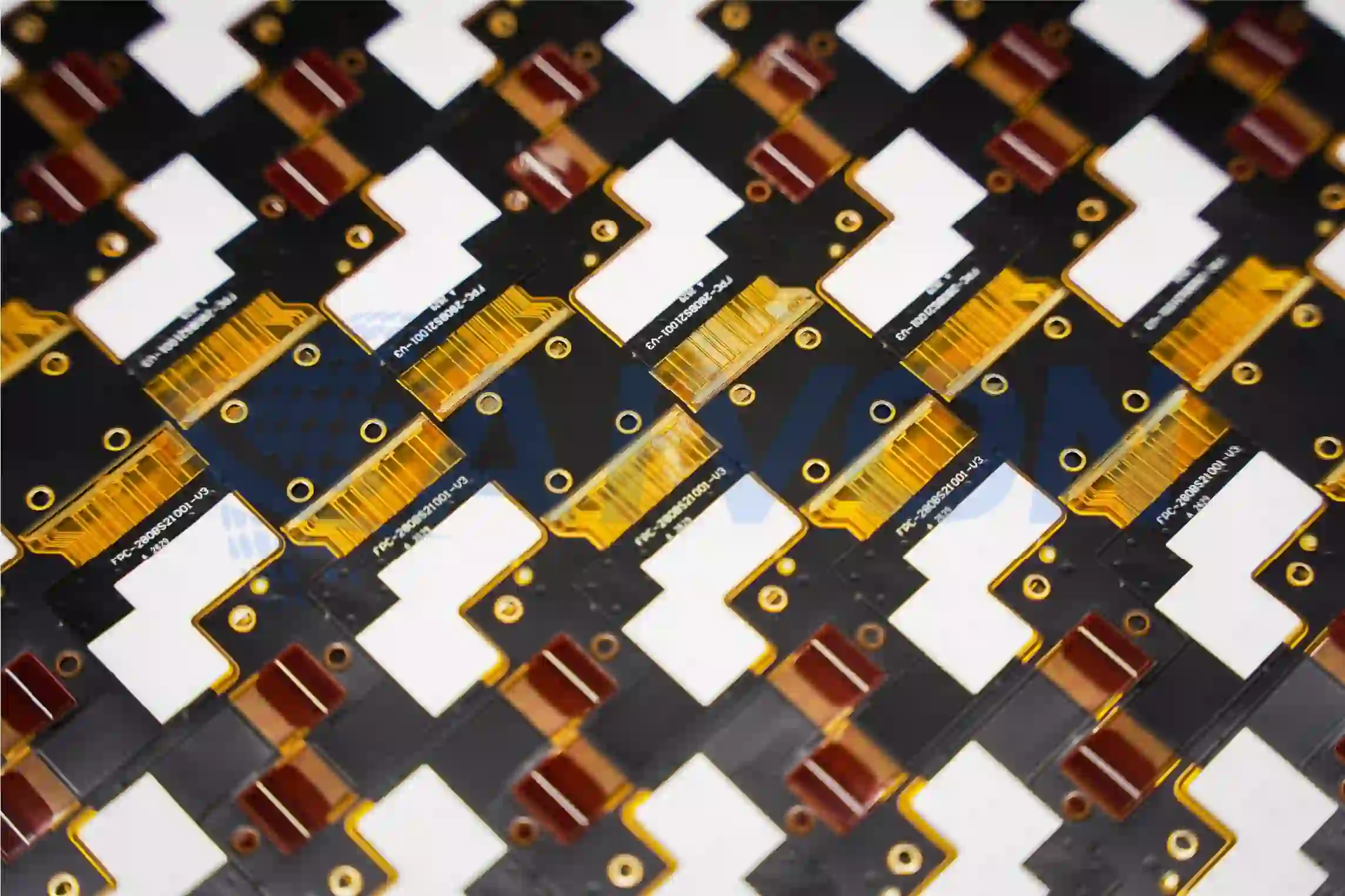
● Immersion Silver (ImmAg): Cost-effective with good conductivity, suitable for high-frequency applications, but more sensitive to tarnishing and handling.
● OSP (Organic Solderability Preservative): Lowest cost, ideal for single-reflow consumer products, but limited shelf life and multiple reflow capability.
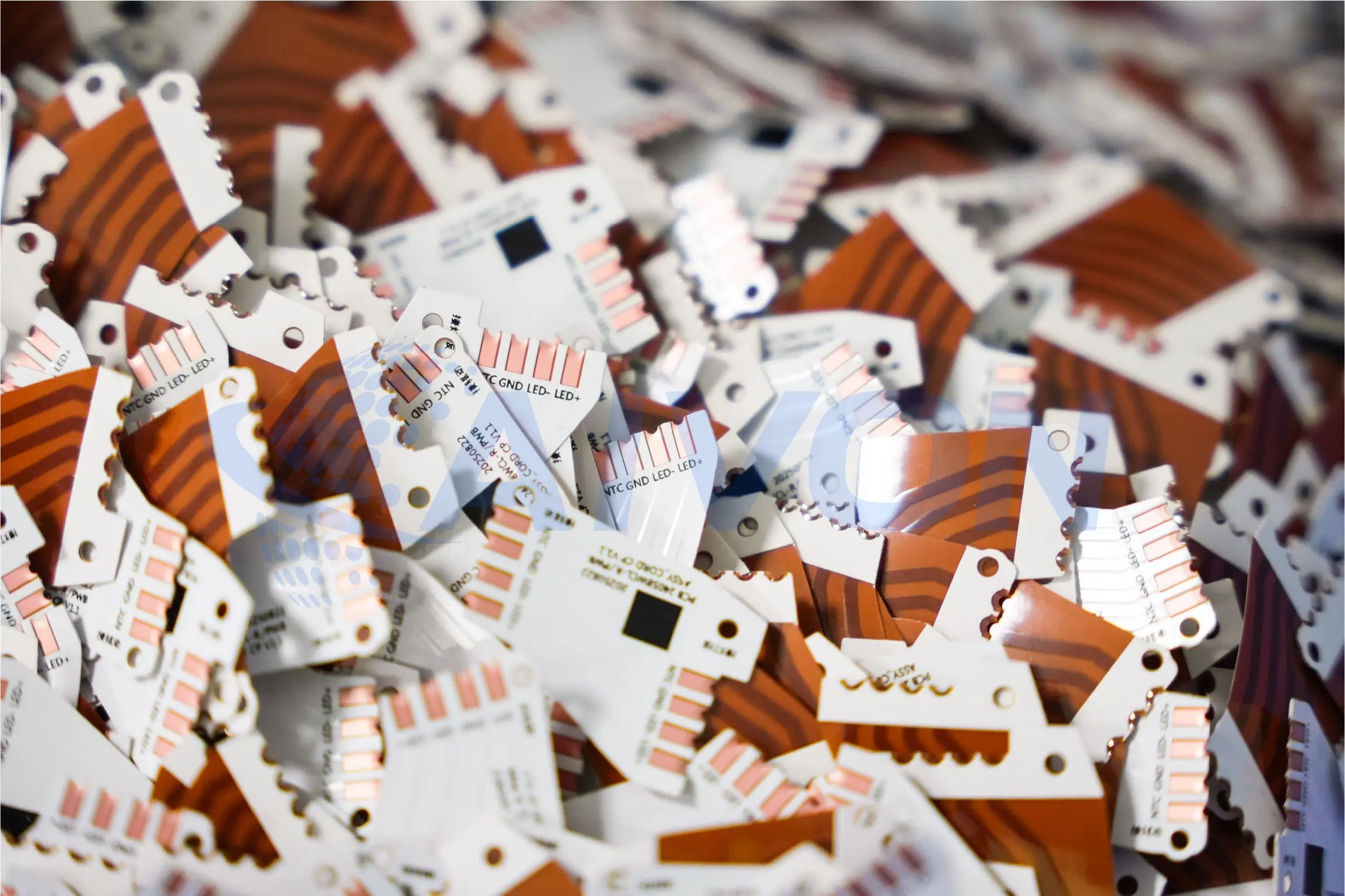
● Immersion Tin: Good for press-fit connectors but prone to whisker growth over time.
Selection depends on assembly process, operating environment, and product lifecycle. For automotive and medical production, ENIG is often mandatory due to its reliability under thermal cycling and humidity exposure.
In dynamic flex areas, the surface finish must not crack or flake during bending. Thinner finishes generally perform better for flexibility but may compromise long-term protection.
Although material selection is fundamental, the final performance of an FPC depends equally on how those materials are processed. Even the best substrate, copper foil, and surface finish combinations can fail if manufacturing controls are not properly maintained. Understanding the fabrication process helps explain how material choices translate into real-world product reliability.
Complete FPC Manufacturing Process and Quality Controls
FPC fabrication involves specialized processes adapted to thin, flexible materials. Each step introduces variables that can affect final product reliability.
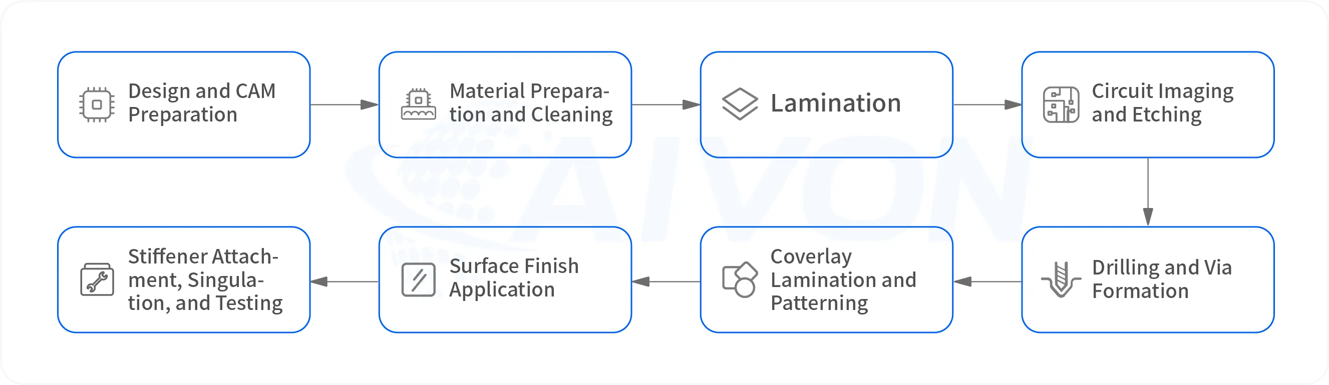
FPC Manufacturing Process Flow:
1. Design and CAM Preparation: Engineering review, impedance modeling, and generation of precise tooling data.
2. Material Preparation and Cleaning: Plasma or chemical cleaning to ensure optimal adhesion.
3. Lamination: Vacuum-assisted bonding of copper to substrate under controlled temperature and pressure profiles. Adhesiveless processes require surface activation.
4. Circuit Imaging and Etching: Application of photoresist, UV exposure through high-precision masks, development, and controlled etching. Fine-line capability reaches 25-50μm lines/spaces in advanced facilities.
5. Drilling and Via Formation: Laser or mechanical drilling followed by desmear and copper plating for multilayer interconnects.
6. Coverlay Lamination and Patterning: Precise alignment and windowing for component pads.
7. Surface Finish Application: Selective plating or immersion processes.
8. Stiffener Attachment, Singulation, and Testing: Precision punching or routing, electrical testing, and AOI inspection.
Quality Control in FPC Manufacturing:
Quality consistency in flexible PCB production depends on tightly controlled process parameters across lamination, imaging, etching, and plating stages. Each CTQ directly impacts dimensional stability, electrical performance, and long-term reliability.
● Lamination temperature uniformity: Ensures stable resin flow and prevents interlayer stress variation, which directly affects warpage and delamination risk.
● Registration accuracy: Critical for multilayer alignment and fine-line circuitry; misregistration can lead to impedance variation and circuit open/short defects.
● Etch rate control to prevent undercutting: Maintains consistent conductor geometry and minimizes lateral undercut, which is essential for impedance control and fine pitch definition.
● Plating thickness uniformity: Directly influences current carrying capability and long-term fatigue resistance, especially in dynamic flex regions.
● Cleanliness levels: Reduces particulate contamination that can cause voids, adhesion failure, or micro-short defects in high-density circuits.
Compliance with IPC-6013, IATF 16949 (automotive), and ISO 13485 (medical) requires extensive documentation, statistical process control, and regular capability studies.
Common Flexible PCB Manufacturing Defects and Their Causes
FPC manufacturing defects can significantly impact product reliability, yield, and overall production efficiency in flexible circuit fabrication. Understanding the most common FPC failure modes, along with their root causes and prevention strategies, is essential for improving process control and manufacturing quality.
1. Dynamic Fatigue Cracking
Root causes: Tight bend radii, repeated flexing cycles, excessive copper thinning(FPC Copper Thinning, Trace Width and Etching Control) during fabrication, uneven copper distribution, or material defects introduced during manufacturing.
Prevention: Use high-ductility RA copper, maintain consistent copper thickness throughout the etching process, optimize plating uniformity, and implement rigorous process controls to minimize stress concentration points.
Manufacturing Consideration: Even when the flex circuit design is mechanically sound, excessive copper reduction caused by over-etching or poor process control can significantly shorten flex life. Variations in trace geometry, copper thickness retention, and etching uniformity may create localized weak points that accelerate crack initiation under repeated bending.
2. Delamination
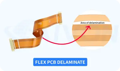
Root causes: Moisture entrapment, inadequate surface preparation, contamination, thermal mismatch between materials, or insufficient lamination pressure.
Prevention: Pre-bake incoming materials, optimize vacuum lamination profiles, implement plasma surface treatment, and conduct routine peel strength verification.
Manufacturing Consideration: Delamination is often linked to inconsistencies in lamination processing rather than material selection alone. Factors such as moisture content, pressure distribution, temperature ramp rates, and adhesive flow behavior directly influence bond integrity and long-term reliability.
3. Copper Cracking at Plated Through Holes (PTH)
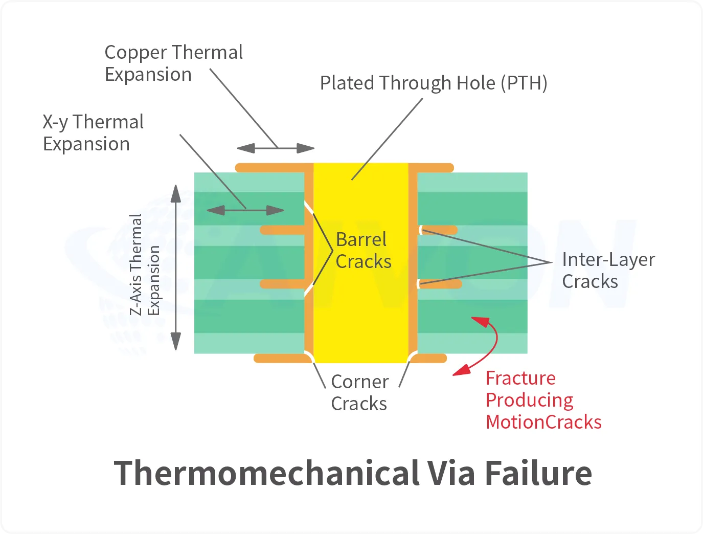
Root causes: Brittle copper deposits, insufficient plating thickness, thermal cycling stress, or defects introduced during drilling and metallization.
Prevention: Optimize copper plating chemistry, maintain uniform plating thickness, improve hole wall preparation, and verify plating quality through cross-section analysis.
Manufacturing Consideration: PTH reliability depends heavily on drilling quality, desmear effectiveness, and copper plating consistency. Variations in hole wall preparation or plating ductility can create stress concentration zones that eventually lead to barrel cracking and electrical failure.
4. Coverlay Voids and Adhesion Failure
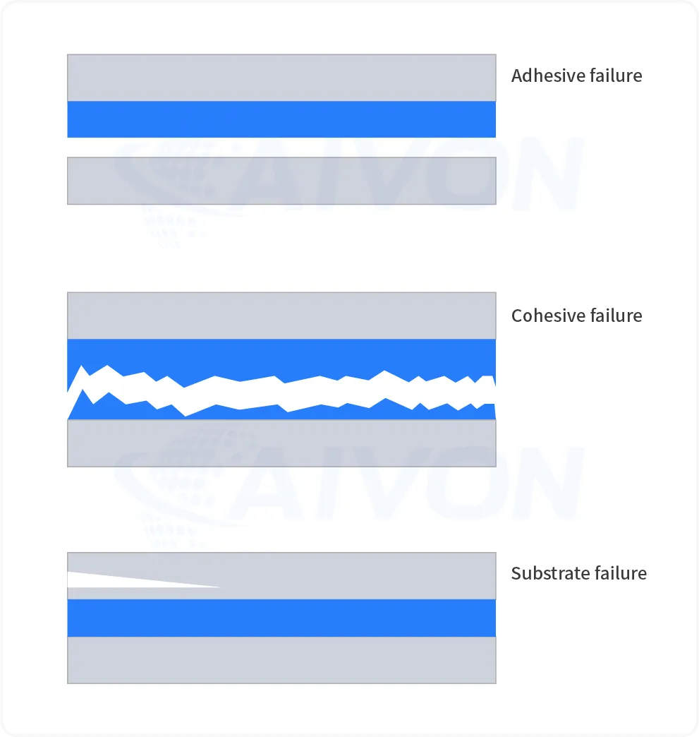
Root causes: Surface contamination, trapped air, improper vacuum lamination settings, adhesive flow issues, or material incompatibility.
Prevention: Implement strict cleaning procedures, optimize lamination pressure and temperature profiles, utilize vacuum-assisted lamination, and perform routine cross-section inspections.
Manufacturing Consideration: Coverlay quality is highly sensitive to lamination conditions. Poor vacuum performance, inadequate adhesive flow, or inaccurate alignment can result in void formation, lifting, and reduced environmental protection of the circuitry.
AIVON Case Study: Coverlay Delamination on Thick Copper FPC
Customer Requirement:
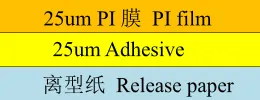
A customer required a 2-layer flexible PCB with a finished copper thickness of 80 μm. The initial design used our standard coverlay construction, model ASC-FC125SKT1, which consists of 25 μm polyimide film with a 25 μm adhesive layer.
Challenge:
After lamination and subsequent processing, localized delamination occurred between the coverlay and the copper surface. In some areas, the coverlay even cracked during handling and assembly. This significantly weakened the mechanical integrity of the flex circuit and posed a reliability risk.
Root Cause Analysis:
The root cause was insufficient adhesive thickness relative to the copper profile. With an 80 μm finished copper thickness, the 25 μm adhesive layer lacked adequate volume and flow capability to properly encapsulate the copper traces and fill the spaces between them. This resulted in reduced bonding area and weak interfacial adhesion. Once delamination initiated, the coverlay lost mechanical support and became prone to cracking under even moderate handling stress.
In practice, we have observed that when finished copper thickness exceeds approximately 50–60 μm, standard 25 μm adhesive coverlay often becomes marginal, especially in designs with dense traces or larger copper features.
Solution:
The coverlay construction was changed from 25 μm PI + 25 μm adhesive to 25 μm PI + 50 μm adhesive. The thicker adhesive provided significantly better resin flow and encapsulation around the thick copper, greatly increasing the effective bonding area and interfacial strength between the coverlay and copper surface.
Result:
After implementing the revised coverlay, the delamination issue was completely resolved. The flex circuits passed subsequent mechanical handling, bending, and reliability verification with no further coverlay-related defects. The change also improved overall structural robustness without compromising flexibility in non-critical areas.
Engineering Note:
This case highlights an important DFM consideration: adhesive thickness in coverlay selection should be evaluated based on finished copper thickness, not just nominal design requirements. For designs with finished copper ≥ 70 μm, we generally recommend evaluating 50 μm adhesive coverlay early in the design stage to avoid adhesion and mechanical strength issues during production and assembly.
Flexible PCB Manufacturing for Different Industries
Flexible PCB for Automotive Electronics
Automotive electronics use flexible circuits in displays, lighting, sensors, battery systems, cameras, and control modules.
Designs in the flexible PCB for automotive should consider temperature changes, vibration, mechanical movement, electrical requirements, and long-term reliability. Material selection and bend-area design are especially important for circuits installed in moving or confined spaces.
Flexible Circuits for Medical Devices
Medical devices often require compact, lightweight, and reliable interconnections.
FPCs may be used in diagnostic equipment, monitoring devices, imaging systems, and wearable medical products. The design should consider cleanliness, insulation, flexibility, biocompatibility requirements where applicable, and the conditions of use.
Flexible PCBs for Wearable Devices
Wearable products require lightweight and flexible structures. The wearable flexible PCB can help connect sensors, displays, batteries, and other compact electronic components.
The circuit should be designed around the product's movement and shape. Bend radius, material thickness, component placement, and protective layers all affect comfort and reliability.
Flexible Circuits for Aerospace and Defense Systems
Aerospace flexible PCB solutions are used in applications where compact routing, weight control, vibration resistance, and stable electrical performance are important. Flexible circuits can help connect components in confined spaces while supporting lightweight and complex system designs.
Material selection and manufacturing controls should be matched to the operating environment. Depending on the application, the aerospace flexible PCB may also require application-specific inspection, environmental testing, and reliability validation.
Flexible PCBs for Consumer Electronics
Consumer electronics commonly use FPCs in phones, tablets, cameras, displays, keyboards, and other compact devices.
These applications often require a balance between thinness, flexibility, fine features, assembly compatibility, and cost.
Flexible Circuits for Industrial and Telecommunications Equipment
Industrial and telecommunications equipment may use flexible circuits for displays, sensors, control panels, connectors, and compact internal wiring.
The material and circuit structure should be selected according to the electrical load, mechanical conditions, temperature, and expected service life.
Rigid-Flex vs Pure Flex Decision Framework:
● Pure Flex: Maximum conformability and lowest weight.
● Rigid-Flex: Better component stability and assembly yields.
● Total cost analysis often favors rigid-flex in complex systems despite higher upfront tooling.
Engineers should conduct thorough design reviews, prototype validation, and supply chain qualification early in the development cycle.
FPC vs Rigid-Flex: Manufacturing and Material Selection Trade-offs
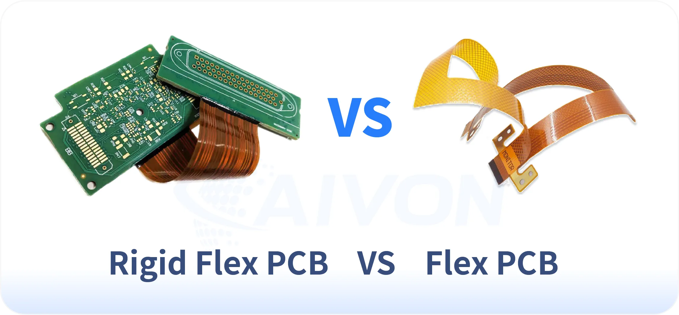
From a production and material selection perspective, choosing between pure Flexible PCB (FPC) and Rigid-Flex constructions involves balancing manufacturing complexity, material cost, process yield, and production scalability.
Pure FPC uses flexible substrates (primarily PI or PET) throughout the entire circuit. Manufacturing is specialized but relatively streamlined, focusing on flexible material handling, precise coverlay alignment, and singulation. Production advantages include lower material diversity, simpler lamination cycles in many cases, and better suitability for high-volume dynamic flex applications. However, attaching components can be more challenging, often requiring additional stiffeners, which adds secondary bonding processes.
Rigid-Flex combines rigid PCB areas (typically FR-4 or high-Tg materials) with flexible PI sections in a single laminated structure. This hybrid approach significantly increases manufacturing complexity. It requires multiple lamination cycles, precise zonal registration between rigid and flex materials, and careful management of CTE mismatch at transition zones. Production yields are generally lower than pure FPC, especially in multilayer builds, due to higher risk of delamination, warpage, and via stress at the rigid-flex interface.
Key Manufacturing and Material Comparison:
|
|
Pure FPC |
Rigid-Flex |
|---|---|---|
|
Material Cost |
Pure FPC is usually lower cost as it uses uniform flexible materials. |
Rigid-Flex requires both rigid laminates and flexible PI films, plus specialized no-flow prepregs, increasing material cost by 40-80%. |
|
Process Complexity |
Pure FPC involves fewer lamination steps. |
Rigid-Flex requires sequential lamination (often 3-5 stages), plasma desmear optimization for different material types, and more stringent registration control (±25μm or tighter). |
|
Production Yield |
Pure FPC typically achieves higher yields (85-95% in mature processes) |
Rigid-Flex yields are lower (70-85%) due to interface challenges, especially in high-layer counts. |
|
Lead Time |
Pure FPC prototypes and production are faster. |
Rigid-Flex often adds 1-2 weeks due to complex tooling and multi-stage lamination. |
|
Scalability |
Pure FPC is easier to scale for high-volume consumer applications. |
Rigid-Flex is better suited for medium-volume, high-reliability programs (automotive, medical, aerospace). |
Conclusion
Successful flexible PCB manufacturing depends on the right combination of materials, circuit structure, fabrication processes, and quality controls.
Polyimide, copper foil, coverlay, adhesives, stiffeners, and surface finishes all influence the performance of the finished FPC. At the same time, trace routing, bend radius, layer registration, lamination, plating, and inspection must be carefully managed during flex PCB fabrication.
Whether the project requires a simple single-sided circuit, a multilayer FPC, a dynamic-flex design, or a rigid-flex structure, early design review and close communication with the manufacturer can help reduce production risks.
By selecting materials based on actual application requirements and validating the manufacturing process before volume production, engineers can achieve more reliable, manufacturable, and cost-effective flexible circuit solutions.
FAQs
Q1: When is RA copper preferred over ED copper?
A1: RA copper is preferred for applications requiring frequent bending or long flex life because of its excellent fatigue resistance. ED copper is generally suitable for static flex designs where cost efficiency is a higher priority.
Q2: How many bend cycles can a quality PI FPC achieve?
A2: A well-designed PI-based FPC can typically withstand more than 500,000 bend cycles, with some dynamic flex applications achieving several million cycles. Actual performance depends on factors such as bend radius, copper type, and circuit design.
Q3: What standards apply to automotive and medical FPC production?
A3: Automotive FPCs are commonly manufactured under IATF 16949 quality systems and IPC-6013 requirements. Medical FPCs typically follow ISO 13485 standards and require enhanced traceability and process control.
Q4: How does coverlay thickness impact performance?
A4: Thicker coverlays provide better mechanical protection and insulation but reduce overall flexibility. Most FPC designs use coverlays between 25 μm and 50 μm to balance durability and bending performance.
Q5: What are typical lead times for custom FPC projects?
A5: Prototype FPC projects typically require 8 to 20 days, while production volumes often take 2 to 5 weeks depending on design complexity and material availability. Early design validation can help shorten development timelines.
Q6: How do material choices affect total project cost?
A6: Material selection influences not only manufacturing cost but also reliability, yield, and product lifespan. Higher-performance materials often reduce long-term failure risks and can lower the overall cost of ownership.
Q7: Are there cost-effective alternatives to FPCs for large EV battery packs?
A7: For large EV battery packs, busbars, wire harnesses, flexible flat cables (FFCs), and modular wiring assemblies may be cost-effective alternatives to FPCs. Busbars are suitable for high-current connections, while wire harnesses and FFCs can support battery monitoring and signal routing. The best option depends on the pack structure, electrical requirements, available space, and assembly process.
Q8: What factors should be considered when selecting FPC materials?
A8: FPC material selection should consider flexibility, bend requirements, operating temperature, electrical performance, mechanical strength, and environmental exposure. The material should match the circuit structure and the conditions expected during assembly and use.
Q9: How can designers reduce the cost of flexible PCB manufacturing?
A9: Designers can help control flexible PCB manufacturing costs by simplifying the circuit structure, avoiding unnecessary tight tolerances, selecting practical material options, and improving panel utilization. Early DFM review can also reduce redesigns and production issues.
Q10: What is the difference between FPC fabrication and FPC assembly?
A10: FPC fabrication produces the flexible circuit itself, including its conductive pattern, insulation, openings, and surface finish. FPC assembly adds components, connectors, or other parts to the fabricated circuit. Some applications require only bare FPCs, while others need a complete flexible circuit assembly.
Q11: How can flexible circuits be protected during installation and operation?
A11: Flexible circuits can be protected through suitable reinforcement, connector support, controlled routing, and secure fixing. Designers should avoid sharp bends, excessive mechanical stress, and unsupported areas that may be damaged during installation or repeated movement.
Q12: What should be considered when choosing an FPC manufacturer?
A12: When choosing an FPC manufacturer, consider its material capabilities, fabrication experience, DFM support, inspection methods, prototype services, production capacity, and quality documentation. The supplier should also be able to meet the reliability and traceability requirements of the intended application.