When a new flexible circuit design lands on your desk, the default choice is still often traditional adhesive FPC. It is familiar, widely available, and usually cheaper on paper. Yet many of those same designs later run into limited bend life, unexpected thickness, thermal bottlenecks, or field delamination. The root cause is frequently the adhesive layer itself.
The decision between adhesiveless FPC (also called no-adhesive flexible PCB) and adhesive FPC is not merely a materials preference. It changes stack-up thickness, dynamic flex capability, heat path, long-term reliability, and total cost of ownership. Both constructions use polyimide and copper, but they bond the copper to the dielectric in fundamentally different ways. That single difference drives most of the performance and cost trade-offs.
Highlights
● Adhesiveless FPC removes the adhesive layer, delivering thinner profiles and significantly higher bend-cycle life.
● Choose no-adhesive flexible PCB when dynamic flex, space constraints, high temperature, or maximum reliability are non-negotiable.
● Traditional adhesive FPC remains the practical choice for cost-sensitive, static, or limited-flex applications with standard lead times.
In this guide you will see exactly how the two constructions differ in structure, what those differences mean for bend performance, thickness, thermal behavior, and reliability, how cost and manufacturing realities play out, and a clear framework for deciding which one belongs in your next design.
What Is Adhesive FPC?
An adhesive FPC is a flexible printed circuit that uses an adhesive layer to bond copper foil with a flexible dielectric material, typically polyimide. The adhesive layer becomes part of the overall FPC stack-up and can affect the circuit's thickness, flexibility, thermal performance, and long-term reliability.
The type and thickness of the FPC adhesive should be selected according to the required electrical, mechanical, and environmental performance of the flexible circuit. For applications involving repeated bending or demanding temperatures, the adhesive needs to be considered together with the copper, dielectric, and coverlay rather than as an isolated material.
How Does Adhesive FPC Construction Work?
In an adhesive-based FPC, an adhesive layer is used to bond the copper foil to the flexible dielectric material. During manufacturing, heat and pressure are typically applied to create a stable bond between the layers.
The adhesive needs to provide sufficient bonding strength while maintaining the flexibility required by the finished circuit. Its thickness, flow characteristics, and compatibility with the dielectric material can all affect the final FPC construction.
What Materials Are Used in FPC Adhesive Systems?
Acrylic and epoxy-based adhesive systems are commonly used in flexible circuit construction. Their properties can differ in terms of flexibility, bonding strength, thermal resistance, and environmental stability.
The appropriate FPC adhesive depends on the application and the complete material stack-up. For example, a circuit designed for repeated bending may require different adhesive characteristics from one designed primarily for static flexing or higher-temperature operation.
What Is Adhesiveless FPC?
An adhesiveless FPC is a flexible circuit that does not use a conventional adhesive layer between the copper foil and dielectric material. Instead, the copper and dielectric are joined through an alternative bonding structure.
By eliminating the conventional adhesive layer, adhesiveless construction can reduce the number of material layers and may provide advantages in thickness, flexibility, and thermal performance.
Adhesiveless FPC vs Adhesive FPC: The Core Difference
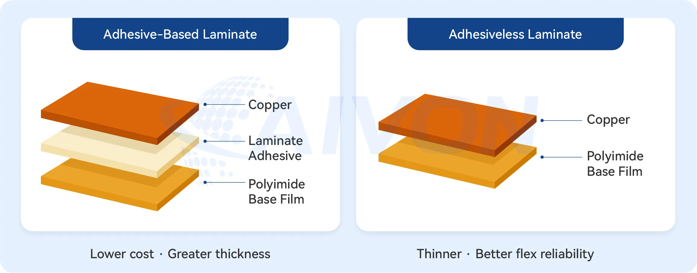
Adhesive FPC is the construction most engineers first encounter. Copper foil is laminated to polyimide film with a discrete acrylic or epoxy adhesive layer. The adhesive provides the bond, but it also adds thickness, compliance, and a potential failure interface.
Adhesiveless FPC, or no-adhesive flexible PCB, eliminates that layer entirely. Copper is bonded directly to the polyimide by casting the polyimide onto copper, by sputtering a thin seed layer and then plating, or by other direct-bond processes. There is no intermediate adhesive.
This difference became more relevant as product requirements tightened. Wearables, foldable devices, medical implants, automotive cameras, and high-density interconnects all pushed designers toward thinner, more flexible, and higher-temperature circuits. Adhesiveless constructions answered those needs and are now routinely available from capable fabricators.
Adhesiveless vs Adhesive FPC Structure Comparison
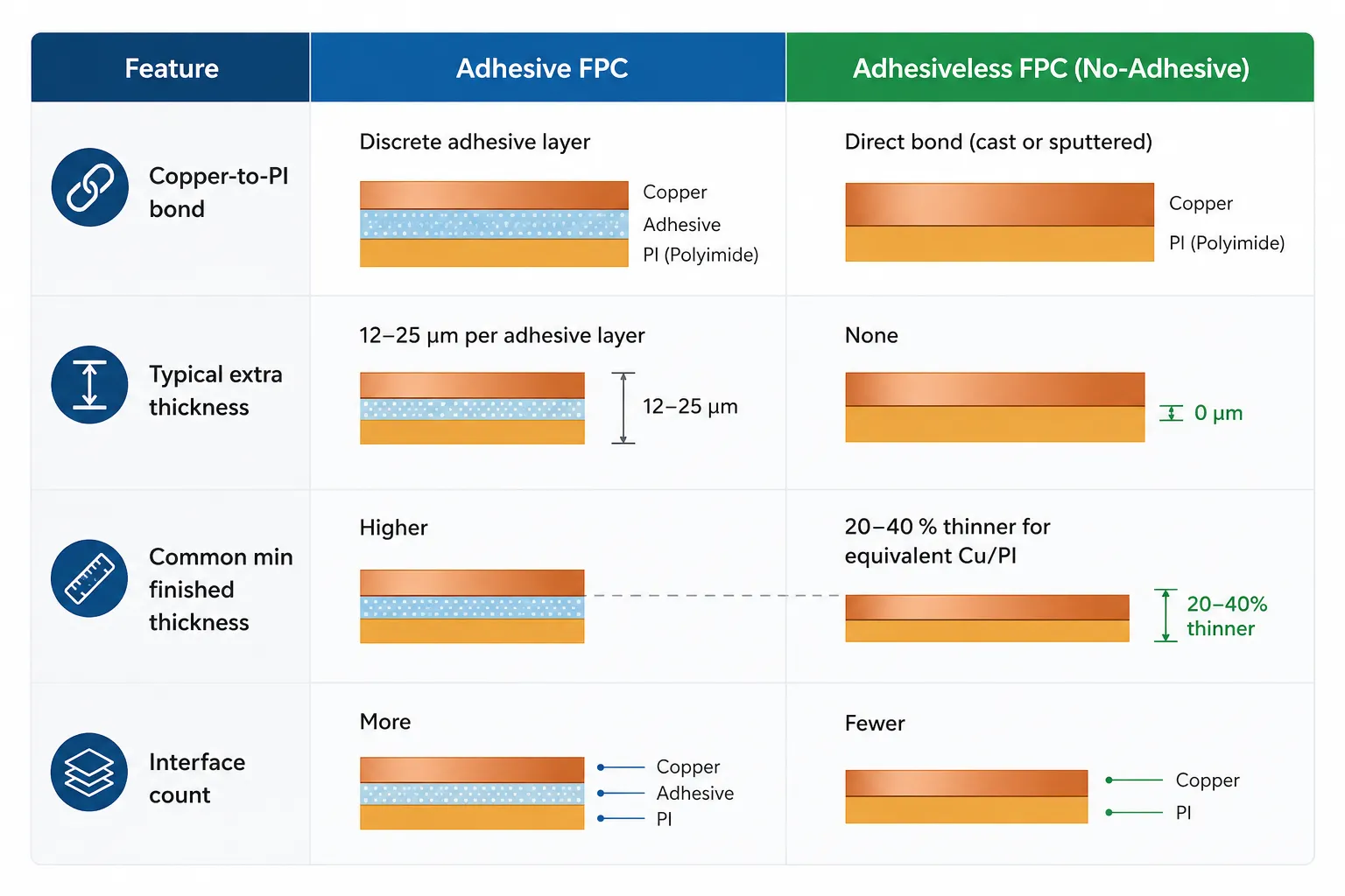
A typical single-sided adhesive FPC contains coverlay adhesive, copper, bond adhesive, and polyimide. A double-sided version multiplies those adhesive interfaces. The adhesive layers contribute both bulk thickness and a soft, relatively low-modulus zone that can move under repeated stress.
An adhesiveless stack-up is simpler: coverlay, copper, polyimide, copper, coverlay. With no adhesive between copper and base film, the circuit is thinner for the same copper weight and polyimide thickness, and the copper-polyimide interface is more intimate.
That intimacy changes mechanical and thermal behavior. Z-axis expansion is lower because the high-CTE adhesive is gone. Interface reliability improves because there is one less material boundary that can absorb moisture, outgas, or delaminate under thermal cycling.
Manufacturing routes also diverge. Adhesive FPC relies on lamination of pre-made copper-clad laminates. Adhesiveless material is produced by casting or sputtering processes that require tighter process control. The result is a cleaner stack-up, but one that some fabricators handle less routinely than standard adhesive material.
Adhesiveless vs Adhesive FPC Performance Comparison
Bend Life and Dynamic Flexibility
The soft adhesive layer is the weak point under repeated flexing. It can crack, delaminate, or allow the copper to migrate over thousands of cycles. Removing it raises the number of bend cycles the circuit can survive before conductor or dielectric failure.
Under comparable copper weight and polyimide thickness, adhesiveless constructions routinely deliver higher dynamic flex life. This makes them particularly suitable for dynamic FPC designs with tight bend radii and continuous-motion applications such as hinge mechanisms, sliding assemblies, and wearable joints. For purely static or very low-cycle bends, the difference is smaller, and adhesive FPC is often adequate.
Thickness and Space Constraints
Eliminating the adhesive layer typically reduces overall circuit thickness by 20–40 % for the same copper and polyimide. In ultra-thin consumer devices, implantable medical electronics, or high-density interconnects where every micron counts, that reduction is decisive. It also improves the circuit' ability to conform to tight three-dimensional shapes without excessive stress concentration.
Thermal Behavior and High-Temperature Performance
Adhesive layers are thermal barriers. Their conductivity is far lower than that of copper or polyimide, so heat flowing through the stack encounters a resistance at each adhesive interface. Adhesiveless FPC removes those interfaces and therefore conducts heat more effectively in the Z-direction.
Continuous operating temperature and glass-transition behavior also improve. Adhesiveless materials generally tolerate higher sustained temperatures, which matters in LED modules, power electronics, automotive under-hood sensors, and high-power RF assemblies. When heat must leave the circuit quickly or the environment is hot, the no-adhesive construction has a clear advantage.
Reliability in Harsh Environments
Moisture absorption, thermal-cycle delamination, chemical attack, and outgassing are all more likely when an adhesive layer is present. In vacuum, medical, or high-reliability aerospace environments, outgassing from the adhesive can lead to critical failures. Choosing adhesiveless flexible PCBs offers distinct advantages for high-performance applications because the copper-polyimide bond is direct and the material set is simpler.
Teams that initially selected adhesive FPC for cost reasons have later redesigned to adhesiveless after field failures linked to delamination or limited flex life. The lesson is consistent: when the environment or the flex requirement is demanding, the adhesive layer becomes a liability.
|
Performance Aspect |
Adhesive FPC |
Adhesiveless FPC |
|---|---|---|
|
Dynamic bend cycles |
Lower |
Higher |
|
Typical thickness |
Baseline |
20–40 % thinner |
|
Thermal path |
Interrupted by adhesive |
More direct |
|
Max continuous temp |
Limited by adhesive |
Higher |
|
Common failure modes |
Delamination, outgassing, moisture |
Fewer interface-related failures |
Cost, Lead Time, and Manufacturing Comparison
Adhesiveless copper-clad laminates and the processes required to fabricate them cost more than standard adhesive materials. At low to medium volumes the unit-price difference is noticeable. At high volumes the gap narrows because material cost becomes a smaller fraction of total cost and yields improve with experience.
Lead times follow a similar pattern. Adhesive FPC benefits from broad material availability and many fabricators who run the process daily. Adhesiveless material can have longer procurement times and fewer qualified suppliers, so schedule risk is higher unless the manufacturer maintains stock or has strong supplier relationships.
In practice, AIVON's prototype FPC projects typically require 8 to 20 days, while production volumes often take 2 to 5 weeks depending on design complexity and material availability. Early design validation helps shorten development timelines and reduces the risk of late-stage changes.
Design-for-manufacturability also differs. Adhesiveless circuits often have tighter process windows for etching, coverlay adhesion, and via formation. Yield can be slightly lower until the fabricator's process is dialed in, which again affects effective cost. Early engagement with the manufacturer helps avoid surprises.
Total cost of ownership is the more useful metric. A higher piece price for adhesiveless FPC can be offset by fewer field returns, a thinner product form factor that enables a better industrial design, or a longer product life in a dynamic-flex application. Pure piece-price comparison often leads teams to the wrong choice.
Adhesive FPC vs. Adhesiveless FPC: Advantages and Disadvantages
Neither construction is universally suitable for every flexible circuit. The appropriate choice depends on the application requirements, material stack-up, manufacturing process, and expected operating environment.
Advantages of Adhesive FPC
Adhesive FPC construction is widely used because it provides an established approach for bonding copper and flexible dielectric materials.
Depending on the selected FPC adhesive, the construction can provide the required combination of bonding strength, flexibility, thermal performance, and environmental resistance for many applications.
It can also offer a broad range of material and manufacturing options, making adhesive-based construction suitable for many prototype and production requirements.
Limitations of Adhesive FPC
The additional adhesive layer increases the overall material thickness and can influence the mechanical and thermal characteristics of the flexible circuit.
The adhesive also needs to remain compatible with the other materials throughout manufacturing and operation. For demanding applications, adhesive properties such as thermal stability, flexibility, and adhesion retention may require additional consideration.
Advantages of Adhesiveless FPC
The absence of a conventional adhesive layer can reduce the thickness of the flexible circuit structure and may provide advantages for applications requiring compact flexible PCB design.
Adhesiveless construction can also eliminate some of the material limitations associated with conventional adhesive layers.
Limitations of Adhesiveless FPC
Adhesiveless FPC construction can require specific materials, manufacturing processes, and process controls. It may also involve different material and production considerations compared with conventional adhesive-based FPCs.
Therefore, the potential benefits of eliminating the adhesive layer should be evaluated against manufacturing requirements, material availability, cost, and application-specific reliability requirements.
Choosing Between Adhesiveless and Adhesive FPC
|
Requirement |
Choose Adhesiveless |
Choose Adhesive |
|---|---|---|
|
Dynamic Flex |
✅ |
|
|
Cost Sensitive |
|
✅ |
|
Ultra Thin |
✅ |
|
|
Medical |
✅ |
|
|
Consumer Electronics |
|
✅ |
|
Static Flex |
|
✅ |
Start with six practical criteria:
1. Required flex PCB bend radius and expected number of flex cycles
2. Maximum allowable finished thickness or space constraint
3. Operating temperature range and need for heat dissipation
4. Environmental or reliability demands (moisture, chemicals, vacuum, medical, high vibration)
5. Budget and expected production volume
6. Lead-time sensitivity
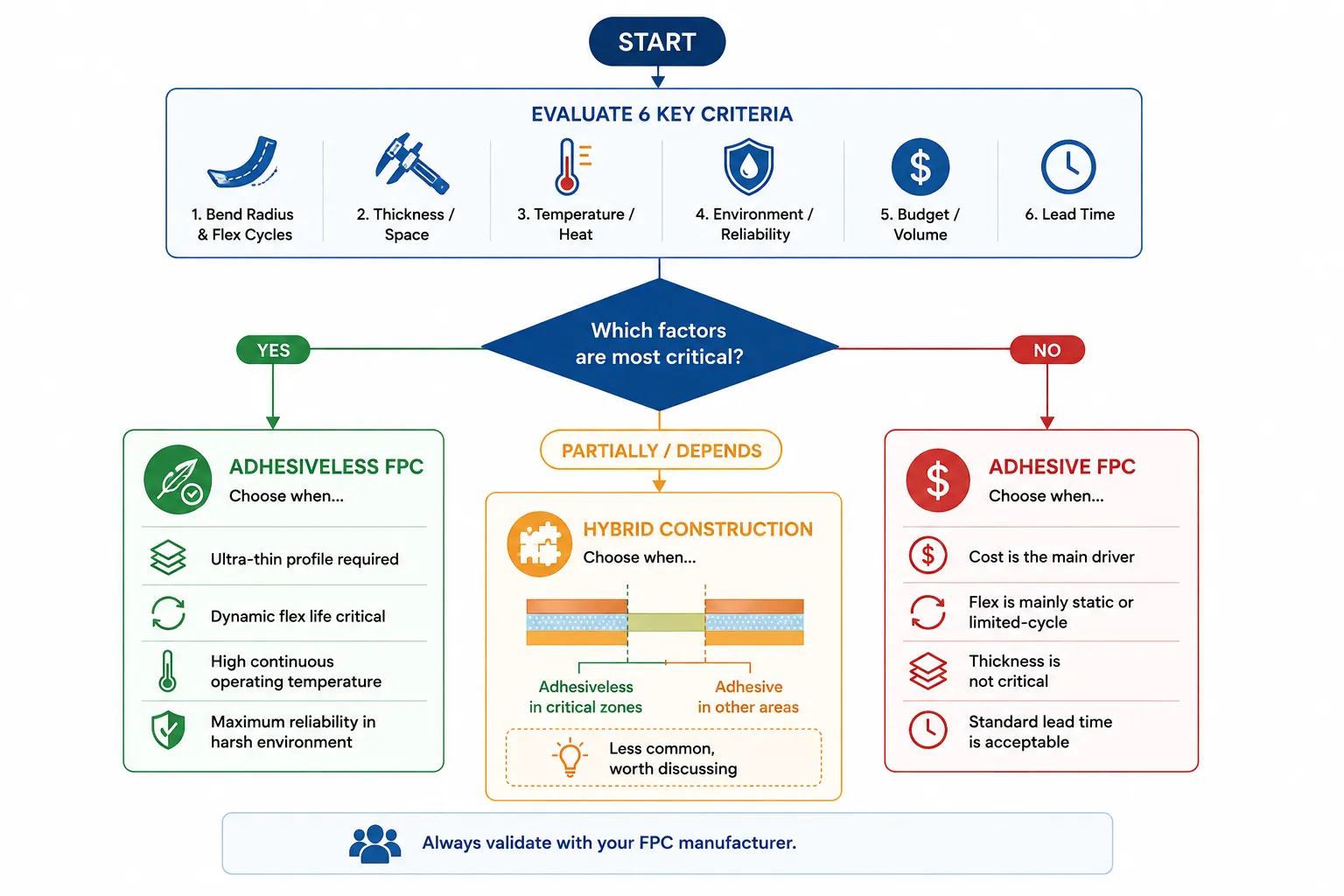
Prefer adhesiveless FPC PCB when any of the following are true: ultra-thin profile is mandatory, dynamic flex life is critical, continuous operating temperature is high, or maximum reliability in a harsh environment is required.
Prefer traditional adhesive FPC when cost is the dominant driver, flex is mainly static or limited-cycle, thickness is not critical, and standard lead times are needed.
Hybrid constructions are sometimes practical. Critical dynamic-flex zones can be built with adhesiveless material while less-stressed areas use adhesive construction, provided the manufacturer can manage the transition cleanly. This approach is less common but worth discussing when the design allows segmented stack-ups.
Typical Applications for Adhesiveless and Adhesive FPC
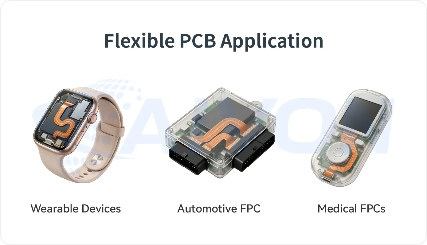
Wearable devices and foldables almost always favor adhesiveless FPC. The combination of continuous motion, tight bend radii, and extreme thickness limits makes the adhesive layer a liability.
Automotive cameras, sensors, and lighting modules often need both thermal performance and long-term reliability under temperature cycling. Adhesiveless constructions handle those conditions more cleanly.
Medical devices, especially implantable or sterilizable ones, frequently specify adhesiveless material to minimize outgassing and improve biocompatibility.
Consumer electronics and cost-sensitive industrial controls still rely heavily on adhesive FPC. When the flex requirement is modest and the budget is tight, the traditional construction remains the rational choice.
Conclusion
Adhesive FPC and adhesiveless FPC use different material structures, and each can be suitable for different flexible circuit requirements. Adhesive construction provides an established approach to bonding copper and dielectric materials, while adhesiveless construction can offer advantages where reduced thickness or specific flexing and thermal characteristics are important.
When making the selection, consider the complete FPC stack-up, including copper, dielectric, adhesive or bonding structure, and coverlay. The required flexibility, thickness, thermal performance, manufacturing process, cost, and long-term reliability should all be evaluated together.
For an adhesive-based design, selecting the right FPC adhesive is an important part of achieving the required balance between bonding performance and flexibility.
FAQs
Q1: Does adhesiveless FPC always have better bend performance?
A1: Adhesiveless FPC generally provides better dynamic flex life under comparable copper weight and polyimide thickness because it eliminates the soft adhesive layer that can crack or delaminate. For static or very low-cycle bending applications, however, the performance advantage is much smaller, and traditional adhesive-based FPC is often sufficient.
Q2: Is adhesiveless FPC more expensive, and by how much typically?
A2: Yes. Both the base material and the fabrication process typically cost more than adhesive-based FPC. The price premium is most noticeable at low to medium production volumes and becomes smaller at higher volumes. However, the lower risk of field failures and the ability to achieve thinner designs can reduce the overall cost of ownership.
Q3: Can I replace an adhesive FPC with an adhesiveless design without changing the layout?
A3: In many cases, the copper layout can remain unchanged, but the stack-up thickness, bend-radius capability, and thermal behavior will differ. Coverlay adhesion, via formation, and impedance characteristics may also require review. Always revalidate both the mechanical and electrical performance before switching to an adhesiveless construction.
Q4: When should I still choose adhesive FPC?
A4: Adhesive-based FPC is a practical choice when cost and lead time are the primary considerations, the application involves static or limited-cycle flexing, board thickness is not critical, and the operating environment does not require the highest level of reliability. In these situations, the traditional construction remains an economical solution.
Q5: Can adhesiveless FPC be multilayer?
A5: Yes. Adhesiveless FPC can be manufactured as multilayer circuits. Multiple adhesiveless copper-clad layers are laminated using specialized bonding films or direct-bonding techniques that avoid the traditional adhesive layer between copper and polyimide. Multilayer adhesiveless constructions are commonly used in applications requiring minimal thickness, improved thermal performance, and high-density interconnects.
Q6: What adhesive is used for bonding flexible PCBs?
A6: Acrylic and epoxy-based adhesive systems are commonly used for bonding flexible PCB materials. The appropriate adhesive depends on factors such as bonding strength, flexibility, temperature resistance, adhesive thickness, and compatibility with the polyimide, copper, and coverlay materials.
Q7: What factors affect FPC adhesive bonding strength?
A7: FPC adhesive bonding strength can be affected by adhesive type, material compatibility, surface condition, adhesive thickness, lamination temperature, pressure, and processing time. Long-term exposure to heat, moisture, chemicals, or repeated flexing can also influence adhesion performance.
Q8: Can FPC adhesive withstand repeated bending?
A8: Some FPC adhesive systems are designed to maintain bonding performance under repeated flexing, but their suitability depends on the adhesive properties and the complete FPC construction. Copper thickness, dielectric thickness, adhesive thickness, bend radius, and expected flex cycles should be evaluated together.
Q9: Does FPC adhesive affect the thickness of a flexible circuit?
A9: Yes. An adhesive layer adds material thickness to the FPC stack-up. Its thickness can therefore affect the finished circuit thickness, bend behavior, and available space within the final assembly. When thickness is tightly constrained, the adhesive layer should be considered during stack-up design.
Q10: How does adhesive thickness affect flexible PCB performance?
A10: Adhesive thickness can influence the overall flexibility, bend behavior, dimensional stability, and thickness of an FPC. The appropriate thickness depends on the bonding requirements and the materials being joined, so it should be selected as part of the complete flexible circuit stack-up.
Q11: What adhesive systems are compatible with flexible circuit applications?
A11: Compatible adhesive systems depend on the substrate, copper foil, coverlay, operating temperature, bending requirements, and manufacturing process. Acrylic and epoxy systems can be used for different flexible circuit applications, but compatibility should be evaluated using the complete material combination rather than the adhesive alone.
Q12: Which low-outgassing adhesive films are suitable for space-qualified flexible printed circuits?
A12: For space-qualified flexible circuits, adhesive films should be evaluated for low outgassing, thermal-vacuum exposure, adhesion retention, and thermal cycling across the required operating range. The appropriate material depends on the specific flexible circuit construction and qualification requirements, so adhesive selection should be based on the complete material system rather than a generic temperature rating.