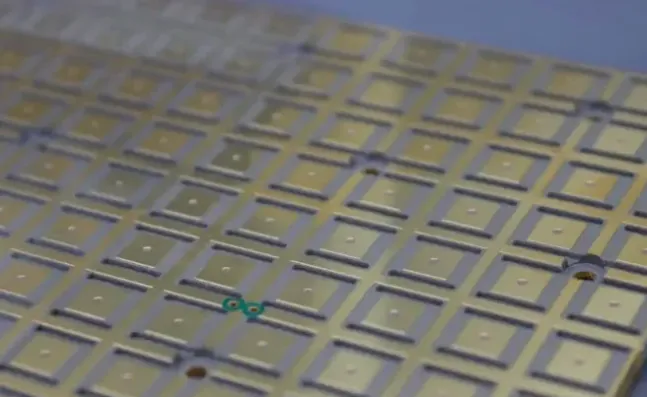
Flexible printed circuits that sail through electrical testing can still crack or delaminate after a few thousand flex cycles in the field. Dimensionally correct parts often create assembly headaches because of minor coverlay wrinkles or registration shifts that only show up under real mechanical stress. These failures are expensive and avoidable.
FPC quality control differs sharply from rigid PCB inspection. Polyimide substrates, coverlay instead of solder mask, thinner copper, and dynamic flex zones introduce mechanical reliability risks that AOI plus ICT alone cannot catch. Effective Flexible PCB inspection therefore centers on four practical pillars: electrical and visual integrity, mechanical bend performance, dimensional accuracy with appearance, and clear mapping to IPC standards. When these are applied with risk-based sampling, most field failures disappear.
Highlights
● FPC quality control rests on four core inspection methods: AOI/X-ray/electrical testing for pattern and hidden defects, bend and flexure testing for mechanical reliability, dimensional and appearance checks for process stability, and strict alignment to IPC-6013.
● Match inspection intensity to real use: high-cycle bend testing for dynamic flex, X-ray for multilayers, and 100% dimensional checks for precision assemblies.
● Treat AOI and electrical testing as the baseline, then add mechanical and dimensional verification based on IPC class and application risk.
In this guide you will see exactly how each of these Flexible PCB inspection methods works, where it is essential, how it maps to IPC standards, and how to convert the four pillars into a clear, usable supplier quality control plan.
Why FPC Quality Control Differs from Rigid Board Inspection
Rigid PCBs live in a static world. Once they are assembled and installed, the main risks are electrical opens, shorts, and soldering defects. Flexible circuits operate under repeated bending, vibration, or even one-time forming during assembly. The base materials are thinner and more sensitive to process variation. Flex PCB coverlay replaces solder mask and must maintain adhesion through thermal cycles and flex. Copper is often rolled-annealed and much thinner, so cracks propagate faster in bend areas. Adhesive or adhesiveless constructions add another variable in dimensional stability after reflow or curing.
The most common field failures unique to FPCs are coverlay delamination, copper cracking in the dynamic flex zone, trace breakage after repeated bending, dimensional drift after coverlay lamination, and contamination trapped under the coverlay. Traditional rigid-board AOI followed by ICT catches pattern defects and netlist problems but misses the mechanical reliability dimension entirely. A board can measure perfect continuity on a flying probe yet fail after 5,000 flex cycles because the copper grain structure or coverlay adhesion was marginal.
From a cost-of-quality view, finding these issues in the field is far more expensive than targeted inspections during production. Scrap and rework at the board house are cheap compared with field returns, warranty claims, or line stoppages at the customer. The right FPC quality control approach therefore adds mechanical and dimensional gates that rigid processes simply do not need.
Flexible PCB Electrical Inspection Methods
Optical and electrical methods form the first line of defense. They catch the majority of FPC manufacturing defects before any mechanical testing begins.
FPC Quality Checklist:
|
Check Item |
Why it Matters |
|---|---|
|
IPC-6013 Compliance |
Basic qualification |
|
AOI Reports |
Pattern verification |
|
Electrical Test |
Net continuity |
|
X-ray Capability |
Hidden defect detection |
|
Bend Testing |
Dynamic reliability |
|
Material Traceability |
Root cause analysis |
|
Dimensional Report |
Assembly fit |
|
Process SPC |
Stable production |
AOI Strengths and FPC-Specific Limits
Automated optical inspection is applied at multiple stages: after etching, after coverlay lamination, and at final inspection. It reliably finds open or short patterns, missing pads, coverlay misalignment, foreign material, and etching undercut or over-etch. Modern systems use high-resolution cameras and multiple lighting angles to handle the translucent polyimide base and the color variations of coverlay.
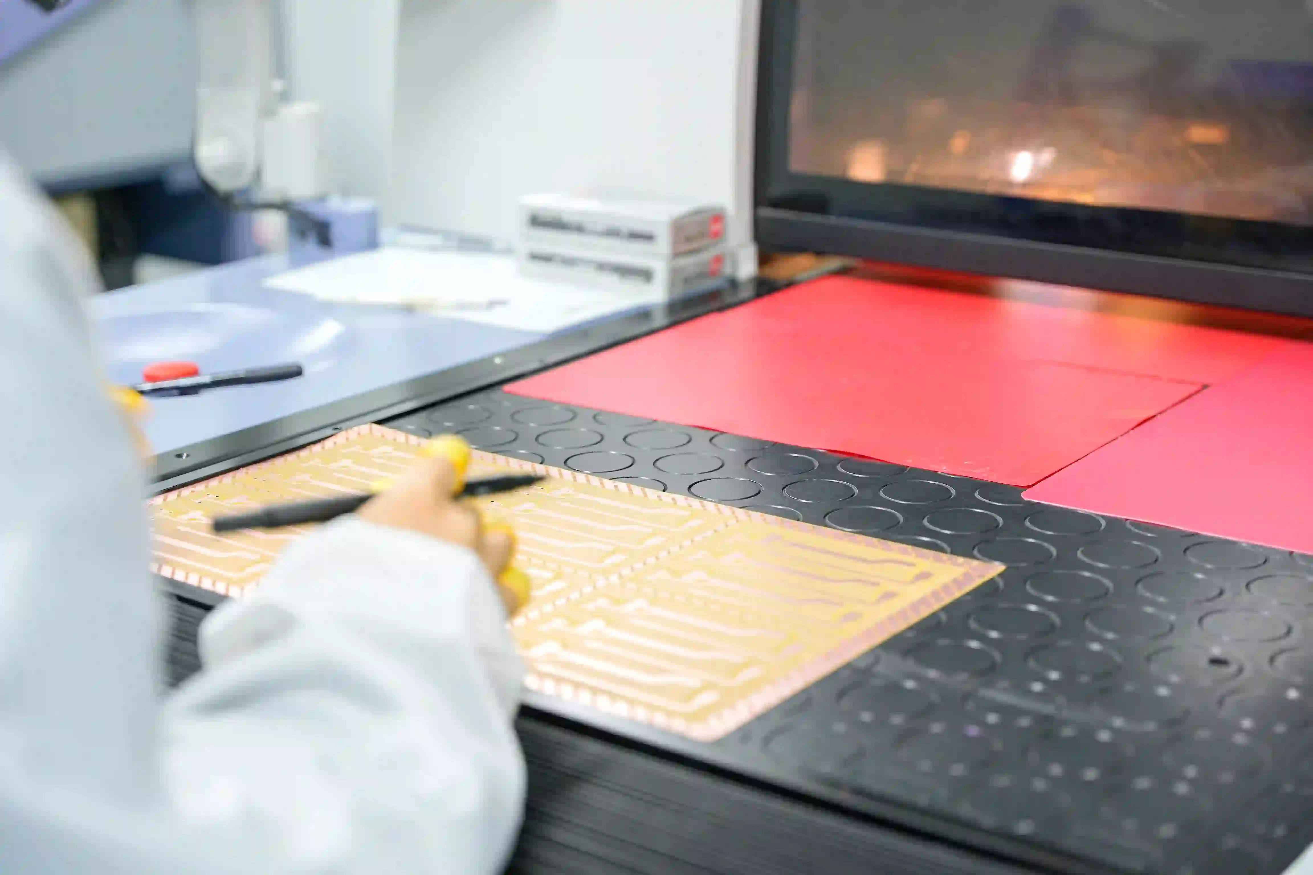
FPC-specific challenges remain. Translucent substrates can create false calls or missed defects if lighting is not tuned correctly. Panel warpage is more common than on rigid boards, so fixtures or vacuum stages are often required. Fine-pitch traces demand higher optical resolution, typically 5–10 µm pixel size or better. Single-sided FPCs are straightforward; double-sided and multilayer constructions need careful registration checks between layers. Rigid-flex parts add the further complication of thickness transitions that can shadow features.
AOI is excellent for pattern and surface defects but cannot see inside vias or under coverlay adhesion voids. It is a necessary baseline, not a complete solution.
When X-Ray Becomes Necessary
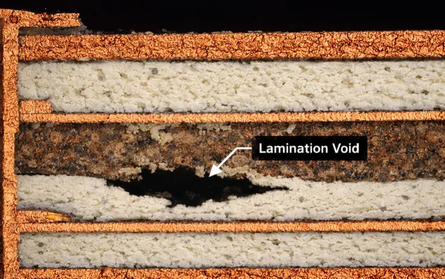
X-ray inspection is mandatory for buried vias, micro-vias, multilayer FPCs, rigid-flex transition zones, and any circuit that already carries components. It reveals plating voids, incomplete via fill, inner-layer misregistration, and solder voids under components that optical methods miss completely.
For consumer electronics, 2D X-ray with sampling is usually sufficient. Automotive and medical applications more often require 3D or CT X-ray on critical vias because the reliability class demands higher confidence. Sampling rates range from 100 % on high-reliability lots to AQL-based checks on high-volume consumer work.
Electrical Testing Options for Flexible Circuits
After optical checks, electrical testing confirms netlist integrity, catches high-resistance opens that AOI may miss, and verifies controlled-impedance traces when required. Fixture-based ICT is fast and thorough for high-volume production but needs careful fixture design. Probe pressure must stay low enough to avoid damaging thin copper or coverlay, and support fixtures are essential to prevent the flexible panel from stretching or tearing under test.
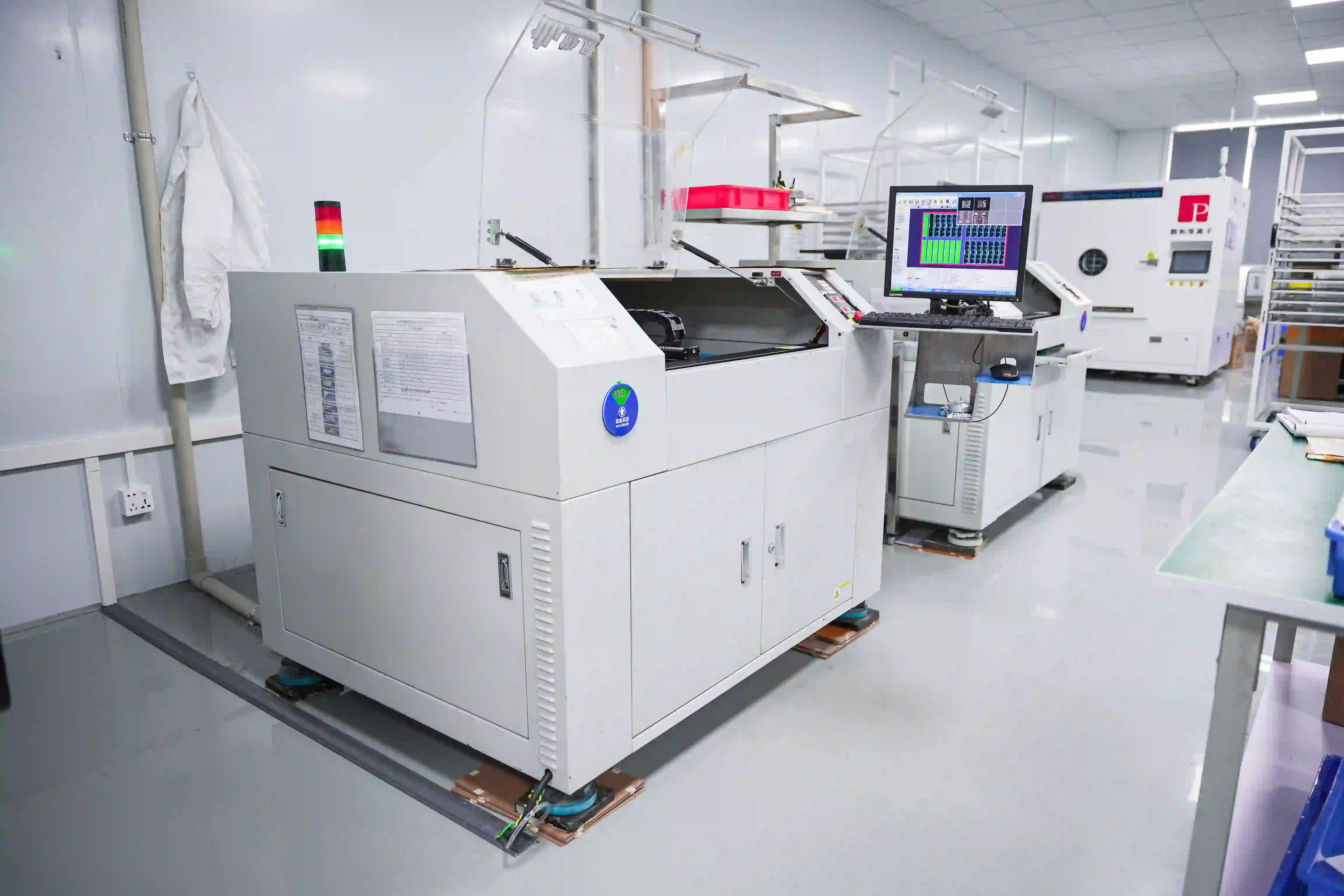
Flying-probe systems are preferred for low-to-medium volume or highly complex nets because they require no hard tooling. They are slower but flexible and safer for delicate FPCs. Recommended coverage targets follow IPC class: Class 2 typically aims for full net continuity plus isolation; Class 3 often adds impedance sampling and higher resistance thresholds.
|
Method |
Detectable Defects |
Typical Stage |
Cost Level |
100 % vs Sampling |
|---|---|---|---|---|
|
AOI |
Pattern opens/shorts, coverlay misalignment, foreign material |
Pre- and post-coverlay, final |
Low–medium |
Usually 100 % |
|
X-Ray |
Via voids, inner-layer misregistration, plating quality |
After plating or lamination |
Medium–high |
Risk-based |
|
ICT / Flying Probe |
Continuity, isolation, high-resistance opens, impedance |
Final electrical |
Medium |
100 % preferred |
FPC Testing Methods for Quality Control
FPC testing is one component of the broader quality control system. While inspection methods such as AOI and dimensional checks focus on identifying manufacturing defects, testing helps verify whether the finished circuit performs as required.
A practical flexible PCB testing process should be based on the FPC's construction, intended application, and applicable quality requirements. Depending on the product, it may combine electrical verification with mechanical, dimensional, and reliability checks.
Electrical Testing for FPCs
Electrical testing is commonly used to verify continuity, isolation, and other defined electrical requirements. It provides a direct way to identify open circuits, short circuits, and other electrical defects that may not be visible during optical inspection.
For production applications, the testing method should provide sufficient coverage without creating unnecessary tooling or handling risks for thin and flexible circuits.
Mechanical Testing for Flexible Circuits
Mechanical testing becomes more important when an FPC will be bent, folded, inserted, or moved during normal operation.
The test conditions should reflect the actual mechanical requirements of the product. Factors such as flex PCB bend radius, flex direction, circuit thickness, copper construction, and expected movement can affect the result.
Application-Specific FPC Testing
Not every FPC requires the same testing program. A static FPC used inside a fixed assembly may require a different validation approach from a dynamic circuit used in a hinge, actuator, wearable device, or other continuously moving application.
For demanding applications, flexible printed circuit board manufacturers may establish additional tests based on expected thermal, mechanical, electrical, or environmental conditions. This helps ensure that the quality control plan reflects the actual risks of the finished product.
How Bend Testing Prevents Flexible PCB Failure
Any FPC that experiences dynamic flexing or even a single static bend during assembly needs mechanical verification. Electrical and optical tests alone cannot predict how the copper and coverlay will survive repeated motion.
IPC-TM-650 Method 2.4.3 covers flexural endurance. Typical customer requirements specify a bend radius of 6–10 times the finished thickness and cycle counts ranging from 1,000 to more than 100,000. The MIT fold test, rolling flex test, and static bend-hold tests are also common depending on the motion type.
A flexible PCB bending test can help determine whether a circuit maintains its required electrical and mechanical performance under defined movement conditions. The test method and acceptance criteria should be established according to the product's intended use rather than based on a single universal condition.
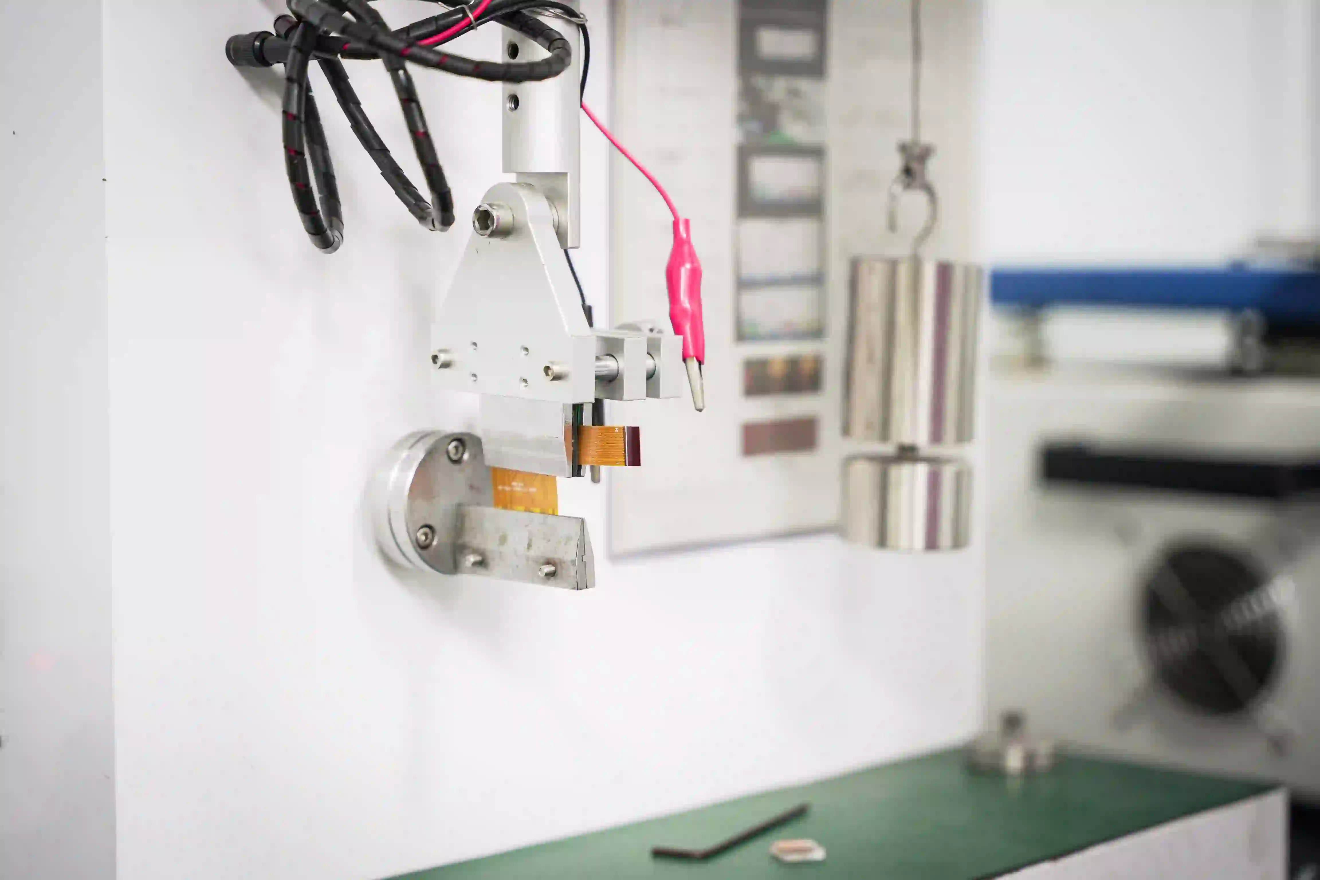
Bending Tests for Flexible PCBs
A bending test can simulate the mechanical movement that an FPC is expected to experience during assembly or operation.
Depending on the application, the evaluation may consider bend radius, bending direction, number of cycles, movement speed, and electrical monitoring during or after testing.
For static applications, the focus may be on whether the circuit can withstand installation at the specified bend radius. For dynamic applications, repeated cycling becomes more important because fatigue can accumulate over time.
What Can Cause an FPC to Fail During Bending?
Several factors can contribute to bending-related failure. These include an excessively tight bend radius, unsuitable copper construction, excessive local stress, poor trace routing through bend areas, and stress concentrations around vias or stiffener transitions.
Material selection and stack-up also influence flex performance. Adhesive layers, coverlay structures, copper thickness, and dielectric thickness can affect how mechanical stress is distributed through the circuit.
When a sample fails a bending test, the failure location should be examined together with the design and construction to determine whether the root cause is related to layout, materials, manufacturing, or test conditions.
Reliability Testing for Flexible PCBs
Flexible PCB reliability testing evaluates whether an FPC can maintain its required performance under conditions that represent its expected service environment.
Depending on the application, reliability verification may include repeated bending, thermal exposure, electrical checks, dimensional evaluation, or other application-specific tests.
The objective is not simply to make the FPC pass a single test. Instead, reliability testing should provide evidence that the selected materials, construction, and manufacturing process can consistently meet the product's expected performance requirements.
Dimensional and Visual Inspection for Flexible PCBs
Dimensional control is tighter on FPCs than on rigid boards because polyimide and coverlay shrink during processing and the CTE mismatch between materials produces measurable drift after reflow or cure. Critical dimensions that routinely need tight control or 100 % checking include outline dimensions and registration to circuitry, hole-to-pad and hole-to-edge distances, coverlay opening registration, stiffener location and adhesive squeeze-out, and overall thickness including coverlay and stiffeners.
Measurement methods range from vision systems for outline and registration, pin gauges for holes, to laser micrometers for thickness. Appearance criteria cover coverlay wrinkles or bubbles, foreign material under or on the coverlay, copper oxidation, edge quality after laser or die cutting, and solderability of exposed pads.
Sampling plans must be documented in the control plan. High-reliability work often uses 100 % inspection for outline and critical registrations; high-volume consumer work may use AQL sampling once process capability is proven. Realistic laser-cut outline tolerances are typically ±0.05 mm to ±0.10 mm depending on material thickness and equipment capability.
Which IPC Standards Apply to FPC Quality Control?
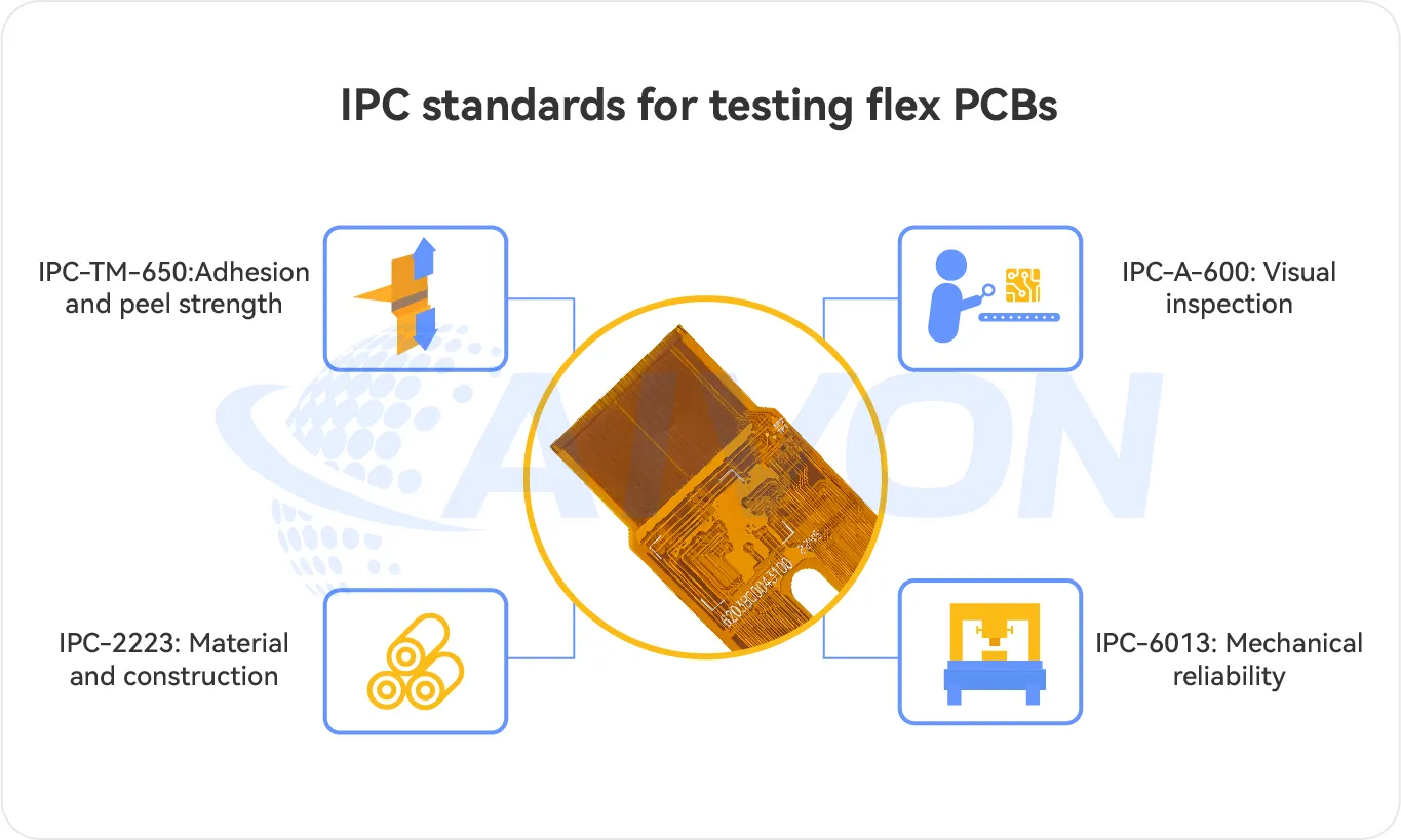
The core documents that define FPC quality expectations are IPC-6013 for flexible printed boards, IPC-A-600 for visual acceptability, the applicable test methods in IPC-TM-650, and IPC-6012 when rigid sections are present in a rigid-flex construction.
|
IPC Standard |
Purpose |
Typical Tests Covered |
|---|---|---|
|
IPC-6013 |
Qualification and performance specification for flexible printed boards |
Electrical continuity, conductor integrity, plated holes, dimensional stability, insulation, flex-specific performance requirements |
|
IPC-A-600 |
Visual acceptability standard |
Surface defects, conductor damage, coverlay quality, solderability, delamination, plating appearance, wrinkles, foreign material |
|
IPC-TM-650 |
Standardized test methods |
Peel strength, thermal shock, dielectric withstand (Hi-Pot), insulation resistance, dimensional stability, copper thickness, impedance, microsection analysis |
|
IPC-2223 |
Design standard for flexible printed boards |
Design recommendations that support reliable testing and manufacturing rather than acceptance testing itself. |
IPC-6013 establishes three performance classes that directly drive inspection intensity:
IPC-6013 defines three classes. Class 1 is general electronic products with the lowest inspection intensity. Class 2 covers dedicated service electronics and is the most common commercial requirement. Class 3 is for high-reliability or life-support applications and demands tighter visual criteria, higher electrical coverage, and more rigorous mechanical verification.
The four inspection pillars map directly onto specific clauses: optical and electrical testing address pattern and conductor requirements; bend testing satisfies the flexibility endurance sections; dimensional and appearance checks cover the workmanship and registration requirements; and overall process control fulfills the qualification and performance sections.
How AIVON Ensures Reliable Flexible PCB Quality
While AIVON manufactures flexible PCBs in accordance with IPC-6013 and IPC-A-600 acceptance criteria, our production process also follows detailed in-house inspection standards to ensure consistent quality throughout fabrication.
Surface integrity is one of the primary inspection focuses. Copper dents, pressure marks that damage conductive traces, and substrate damage are not accepted. Scratches are evaluated not only by their appearance but also by their depth and impact on the copper layer. Minor surface scratches may be accepted only when they do not expose the underlying base material or reduce the copper thickness beyond defined internal limits.

Because flexible circuits are designed to bend repeatedly, mechanical integrity is equally important. Inspectors carefully examine each panel for creases, fold marks, and stress damage. Sharp creases or permanent folds that could become crack initiation points during repeated flexing are rejected, while only a limited number of shallow U-shaped creases are permitted under controlled acceptance criteria.
Hole quality is verified after drilling to ensure reliable electrical performance. Burrs around plated holes are removed through controlled deburring processes and inspected by both visual examination and touch to confirm a smooth finish. Hole deformation is not permitted, and drill registration is closely checked to prevent conductor breakout or insufficient annular ring connections that could affect circuit reliability.
Rather than relying solely on final inspection, these quality checkpoints are integrated throughout production, allowing potential defects to be identified and corrected before they progress to subsequent flexible PCB manufacturing stages. This combination of IPC compliance and process-specific quality control helps ensure that every flexible PCB meets both industry standards and the mechanical reliability required for demanding applications.
|
Inspection Focus |
AIVON Internal Control |
|---|---|
|
Surface Damage |
No copper dents, substrate damage, or exposed base material; scratches evaluated by depth and copper impact |
|
Mechanical Integrity |
Sharp creases and permanent folds rejected; limited shallow U-shaped creases accepted |
|
Hole Quality |
No hole deformation; burrs removed and verified by visual and tactile inspection |
|
Drill Registration |
No conductor breakout; sufficient copper connection maintained around drilled holes |
|
Process Control |
Quality checkpoints integrated throughout fabrication rather than relying only on final inspection |
Conclusion
Effective FPC quality control is built on four complementary inspection pillars: electrical and visual methods (AOI, X-ray and continuity testing), mechanical bend and flexure testing, dimensional accuracy together with appearance checks, and clear alignment to IPC-6013 and related standards. Each pillar targets failure modes that rigid-board processes never encounter. The practical goal is not to apply every possible test to every board, but to match the right combination of inspections to the real risks of the application—static or dynamic flex, consumer, automotive or medical, IPC class 2 or class 3.
For flexible circuits exposed to repeated movement, bending and reliability testing can provide additional information about mechanical performance. For complex structures, AOI, electrical testing, X-ray inspection, and dimensional verification can work together to identify defects that may not be visible through a single inspection method.
The most effective approach is to establish the inspection and testing plan around the actual FPC design, manufacturing process, application, and applicable quality requirements. This helps manufacturers identify problems earlier, maintain consistent production quality, and reduce the risk of failures after shipment.
FAQs
Q1: What is the practical difference between AOI and visual inspection for FPCs?
A1: AOI uses automated cameras and algorithms to inspect pattern integrity, registration, and surface defects with high speed and consistent criteria. Visual inspection relies on trained operators using magnification and is better suited for evaluating subjective appearance issues such as coverlay wrinkles or color variation. In most production environments, AOI serves as the primary inspection method, while visual inspection is used for secondary verification or quality audits.
Q2: Is X-ray inspection required for every multilayer FPC?
A2: No. X-ray inspection is typically required only for designs with buried vias, microvias, rigid-flex transitions, or when higher reliability standards—such as IPC Class 3, automotive, or medical applications—require verification of internal plating quality. For simpler double-sided or low-layer-count multilayer FPCs, sampling inspection or demonstrated process capability is often sufficient.
Q3: Which IPC class is appropriate for a medical wearable device?
A3: Most medical wearable devices are designed to meet IPC Class 3 requirements because they demand high reliability and may involve patient contact or critical medical functions. However, the final IPC class should be determined through regulatory requirements, risk assessment, and any additional customer or ISO standards.
Q4: Can flying-probe testing replace fixture ICT for low-volume FPCs?
A4: Yes. Flying-probe testing is often the preferred solution for low- to medium-volume production or complex FPC designs because it eliminates fixture tooling costs and reduces the risk of mechanical damage from test probes. For high-volume manufacturing, fixture-based ICT is generally faster and more cost-effective once the tooling investment is justified.
Q5: What should be included in an FPC quality control plan?
A5: An FPC quality control plan should define the materials, critical dimensions, manufacturing checkpoints, inspection methods, test requirements, acceptance criteria, and documentation needed for each production stage. The plan should be tailored to the FPC's construction, application, production volume, and customer requirements rather than using the same controls for every flexible circuit.
Q6: How often should FPC quality inspections be performed?
A6: Inspection frequency depends on the manufacturing stage, process capability, product requirements, and risk level of the FPC. Some checks may be performed on every board, while others can be based on defined sampling plans. Critical characteristics should have clearly documented inspection frequencies and acceptance criteria.
Q7: What happens if an FPC fails a quality inspection?
A7: A failed FPC should be identified and segregated according to the manufacturer's nonconformance procedure. The issue can then be reviewed to determine its cause, scope, and impact on the affected lot. Depending on the defect and customer requirements, the material may be reworked, retested, rejected, or subject to an agreed corrective action.
Q8: How can manufacturers reduce recurring FPC quality problems?
A8: Recurring quality problems are best addressed by identifying their root causes rather than repeatedly correcting individual boards. Manufacturers can review defect patterns, process conditions, material records, inspection results, and design characteristics to determine where variation is being introduced. Corrective actions can then be applied to the relevant manufacturing step and monitored for effectiveness.
Q9: Does FPC quality control change for different applications?
A9: Yes. Quality control requirements can vary significantly depending on how the FPC will be used. A circuit for a static internal connection may have different critical characteristics from one used in an automotive, medical, aerospace, or continuously moving application. The inspection and documentation requirements should therefore reflect the product's operating conditions and applicable specifications.