 00:53
EMI Reduction
Electromagnetic interference (EMI) poses a significant challenge in modern electronics design, where unwanted signals can disrupt circuit performance, lead to compliance failures, or cause system malfunctions. The EMI Reduction tag on this blog aggregates expert insights and practical strategies to help engineers and hobbyists effectively minimize these issues in printed circuit boards (PCBs) and electronic assemblies. By focusing on proven methods, this collection addresses the core needs of professionals seeking to enhance signal integrity, meet regulatory standards like FCC or CE, and optimize device reliability in noisy environments. Key topics under EMI Reduction include essential techniques such as proper PCB layout optimization, where trace routing and component placement play critical roles in reducing crosstalk and radiated emissions. Grounding practices, for instance, involve creating low-impedance paths to shunt noise away from sensitive areas, while shielding enclosures and ferrite beads offer straightforward ways to suppress high-frequency interference. Readers will find discussions on filtering solutions, like using capacitors and inductors to attenuate unwanted frequencies, alongside real-world case studies that demonstrate how these approaches resolve common problems in consumer electronics, automotive systems, and industrial controls. For those troubleshooting persistent EMI issues or designing new prototypes, the articles here provide actionable steps, from selecting appropriate materials to simulating designs with tools like SPICE or electromagnetic field solvers. Implementing these best practices not only prevents costly redesigns but also ensures robust performance in electromagnetic compatibility (EMC) testing. As you delve into the posts linked below, you'll gain the knowledge to apply these concepts directly to your projects, fostering innovation in interference-free electronics.
Video Guide

Technical Articles
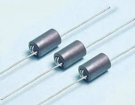
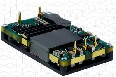
Understanding Ground in Electronic Circuits: Digital Ground vs. Analog Ground
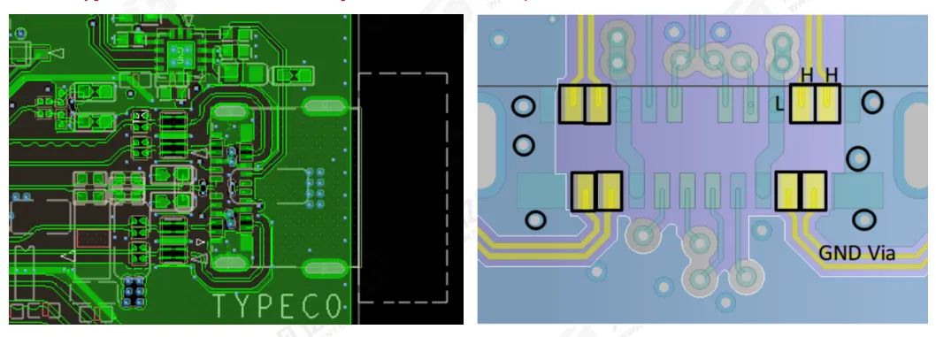
PCB Layout and Routing Requirements for USB 2.0, USB 3.0, and USB Type C Interfaces

Should You Use Solid or Hatched Copper Pour on PCBs?
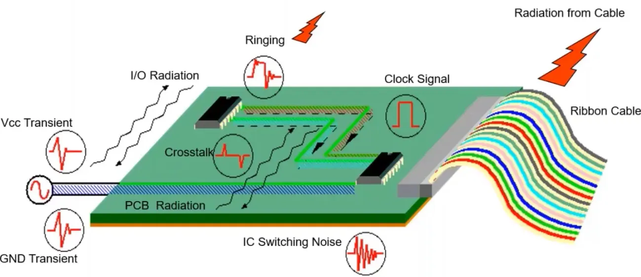
Nine Practical Rules for EMI Control in High-Speed PCB Design
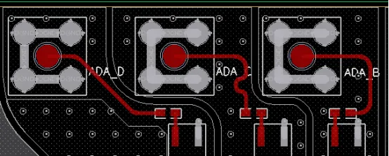
Mitigating Interference in Mixed-Signal PCB Design
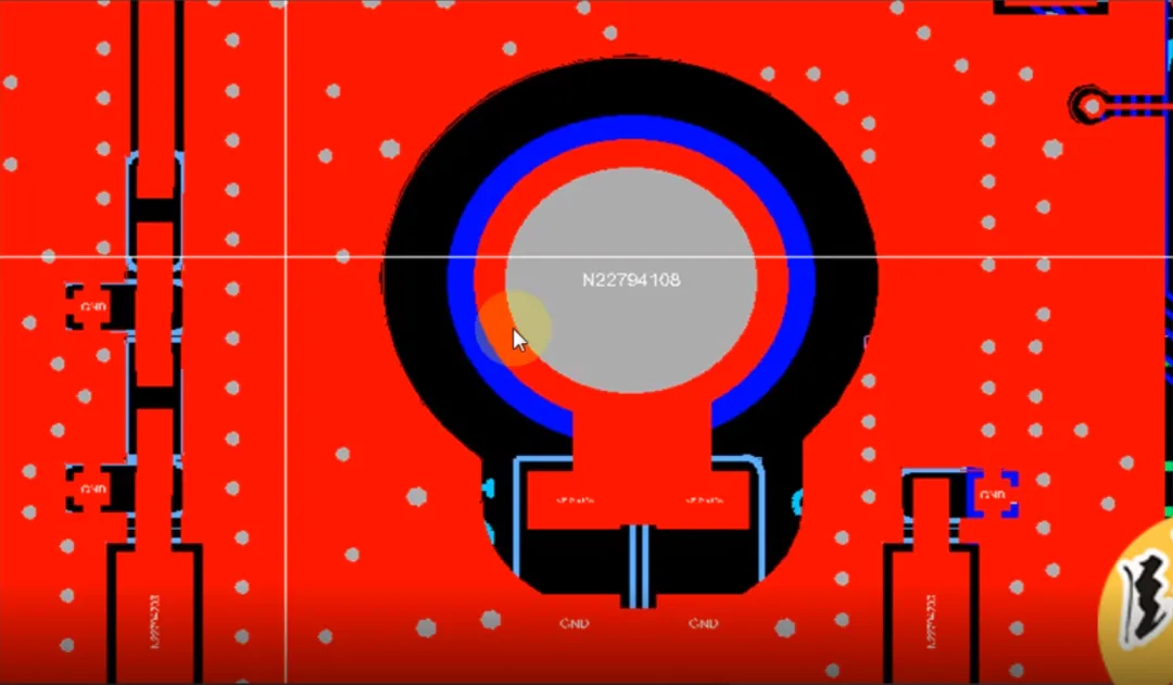
Why Designers Often Tie PCB Ground to Chassis Ground with a Parallel Resistor and Capacitor
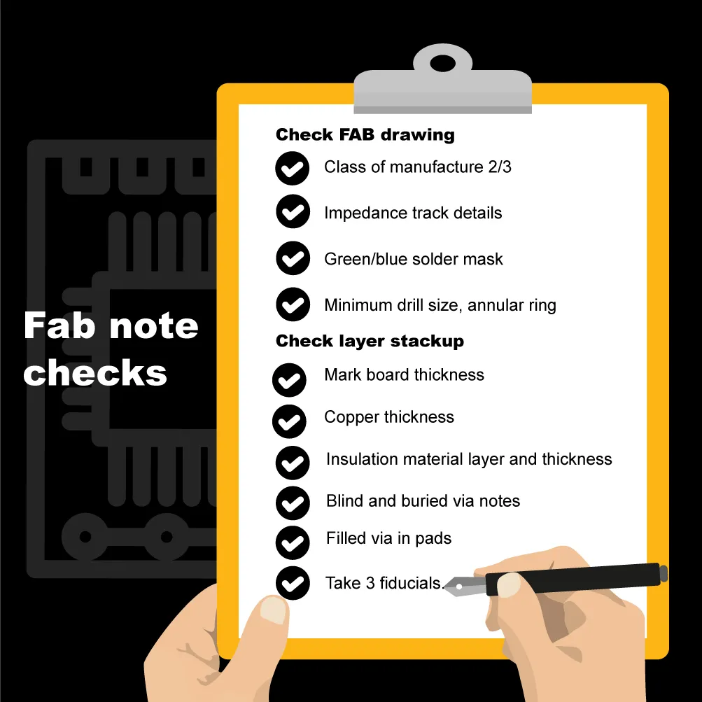
PCB Design Checklist: Design Inputs, Templates, Clock Placement, and Mechanical Controls

High-Speed vs. Analog Signal Interference: Practical PCB Design Solutions

Do You Need a Full-Board Copper Pour on Your PCB?

Why Power Planes Are Set Back in Multilayer PCB Design: The 20H Rule Explained
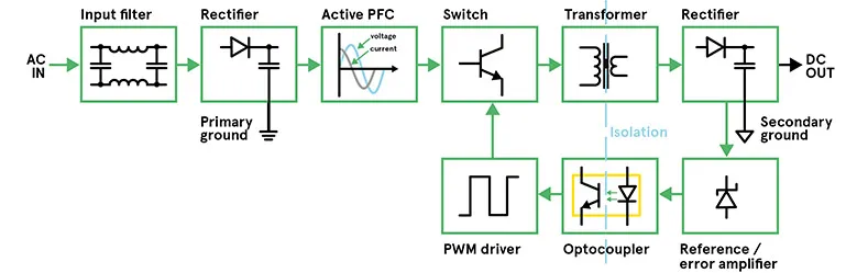
Twelve Switching Power Supply Topologies and How to Calculate Them
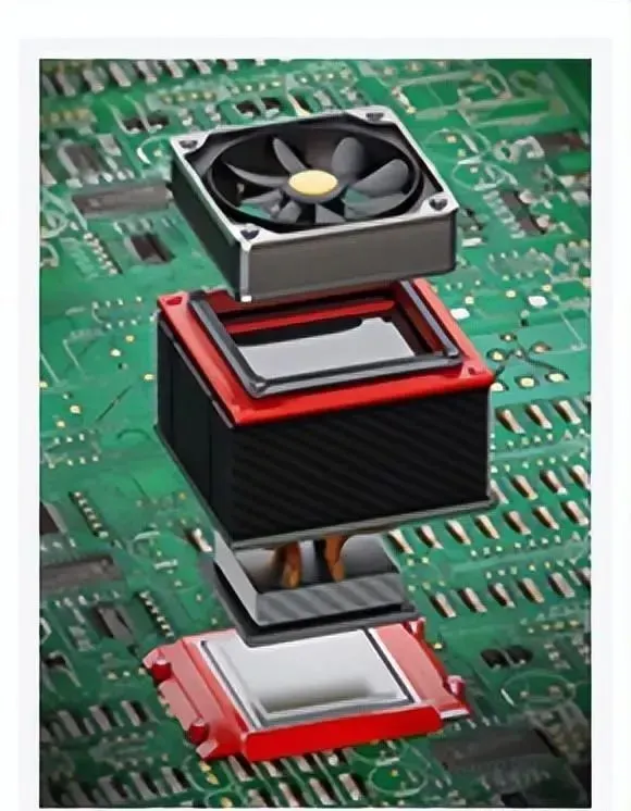
Summary | 7 Key Points in PCB Power Design
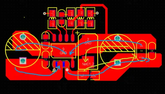
Ground in Electronic Circuits: Signal Ground, Power Ground, Ground Partitioning, Guard Ground, and Single-Point Grounding
PCB Layout Design Essentials and Practical Techniques
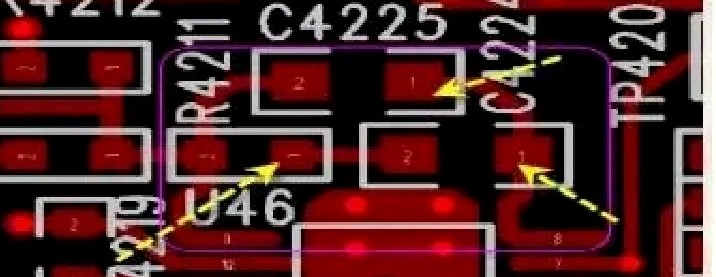
Power Module PCB Design: From Theory to Practice
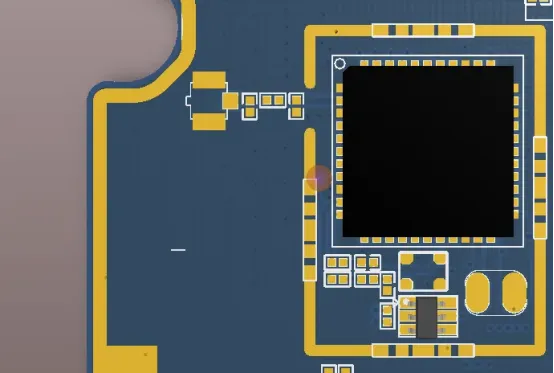
A PCB Shield Can Is Not Just a Metal Lid
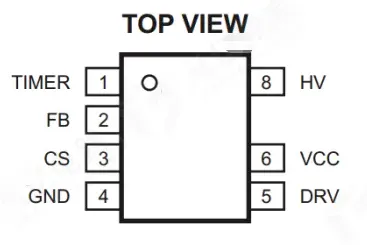
AC-DC Power Conversion: Circuit Methods, HFC0500 Example, and PCB Layout Rules
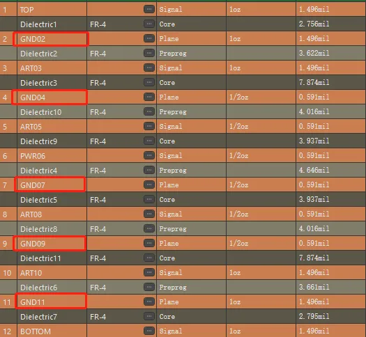
Stack-up Principles for Multilayer PCB Design
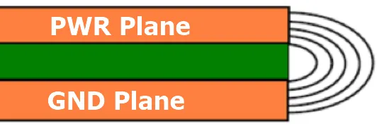
Why the Power Plane Should Be Smaller Than the Ground Plane