PCB Thermal Design
Effective thermal management is a critical aspect of printed circuit board (PCB) design, ensuring that electronic components operate within safe temperature ranges to prevent failures, extend lifespan, and maintain performance. In the realm of PCB Thermal Design, engineers and designers focus on strategies to dissipate heat generated by high-power components, such as processors, power amplifiers, and LEDs. This involves selecting appropriate materials with high thermal conductivity, optimizing board layout for airflow, and incorporating features like thermal vias, heat sinks, and copper pours to enhance heat transfer. For those searching for PCB Thermal Design resources, this tag serves as a comprehensive hub for practical guidance tailored to real-world challenges. Whether you are troubleshooting overheating issues in consumer electronics, automotive systems, or industrial equipment, the content here delves into best practices that can be directly applied to your projects. Key topics include thermal simulation techniques using software tools like ANSYS or Altium, guidelines for multilayer board configurations to minimize thermal resistance, and case studies demonstrating how effective design choices have resolved common problems such as hot spots and thermal runaway. Understanding these principles not only helps in complying with industry standards like IPC-2152 for current-carrying capacity but also empowers you to innovate in designs that demand higher efficiency and reliability. By exploring the articles grouped under this tag, you can gain actionable insights into advanced methods, such as integrating phase-change materials or active cooling solutions, and learn from expert analyses of thermal modeling errors to avoid. This collection equips you with the knowledge to refine your PCB designs, ultimately leading to more robust and efficient electronic products.
Technical Articles
Single-Cell Li-ion Circuit for Stable 5V Output

Solar PCB Design Solutions for High Efficiency Photovoltaic Systems
Buck Converter Using TI TPS5320
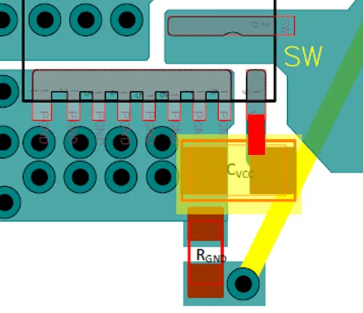
Key PCB Layout Guidelines for Buck Converters
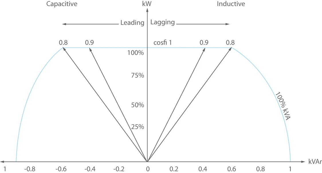
What Is Power Factor? UPS Power Factor in UPS Systems: Load PF Explained for Reliable Power Electronics DesignPower Factor Guide
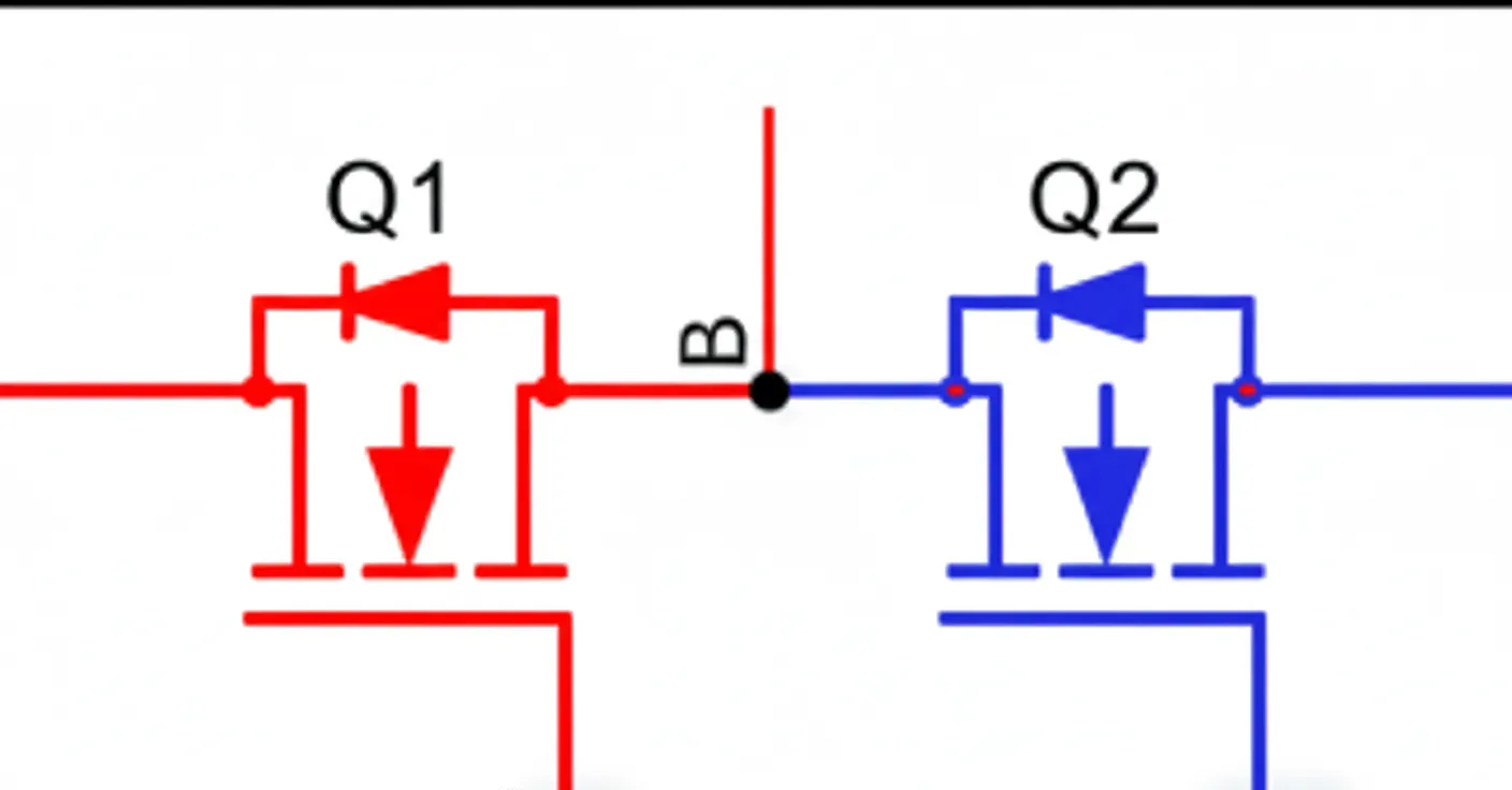
Why a Bootstrap Capacitor C1 Is Used in Buck Converters
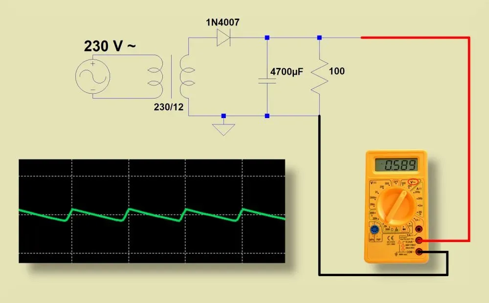
Power Supply Ripple: Measurement and Suppression Methods
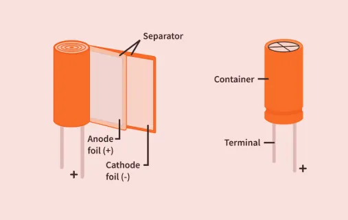
Why Parallel Power Capacitors Often Use a 100x Ratio

PV Power Forecasting System Architecture
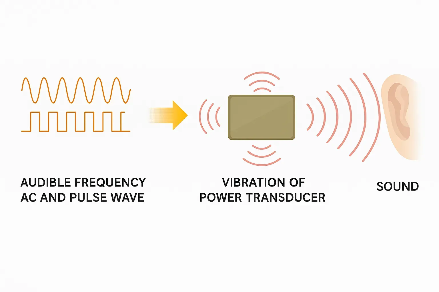
Why Power Inductors in DC-DC Converters Squeal
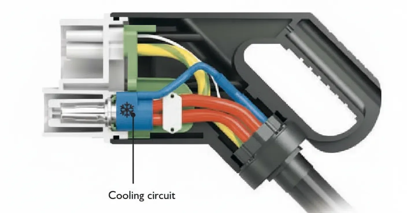
EV DC Charging Module: Functional Diagram, Power Electronics, and PCB Design Insights
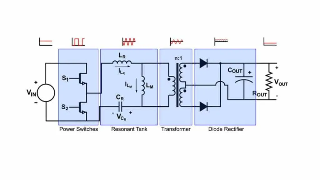
12 Operating States in High-Power LLC Design
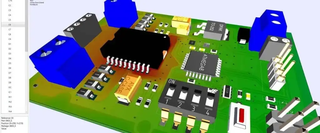
Optimizing Performance: Thermal Management in Industrial Automation Controller PCBs
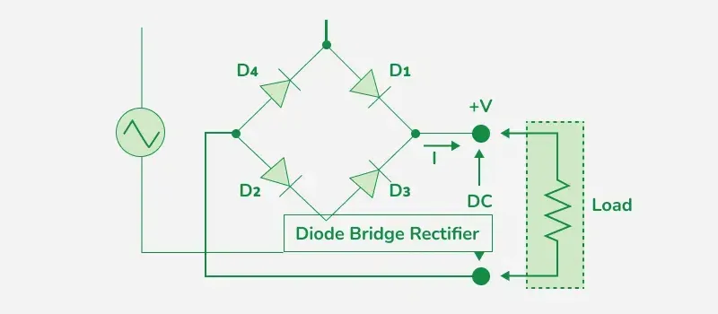
Effects of a Delta Bridge Rectifier Failure on a Circuit
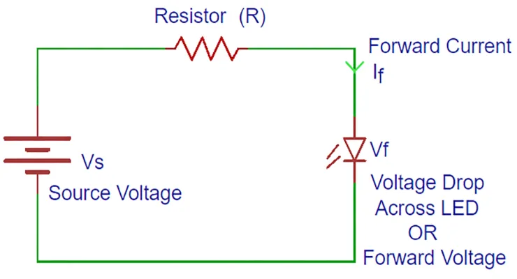
Is a Current Source Absorbing or Delivering Power
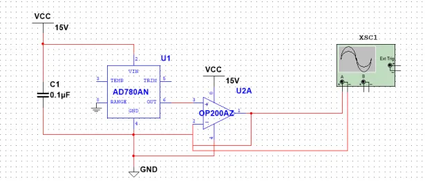
BUCK Converter Design Explained
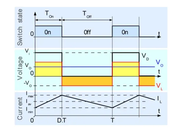
Adaptive Mode for Buck Converter Efficiency

Solid-State Battery Development Still Faces Major Challenges