A 2-layer flexible circuit measuring 130 mm by 600 mm presents a distinct set of production-preparation challenges. The customer data specified rolled copper, white coverlay on both sides, OSP finish, laser forming, and V-cut depanelization in a 20 × 1 customer self-panel arrangement with zero process edge. Quantity was 100 pieces supplied as 5 sets. While the electrical design was complete, the manufacturing package could not be released until three linked production issues were resolved: absence of edge protection at both ends of the long strip, inability of the stated 0.2 mm thickness to accommodate the white coverlay, and silkscreen characters too small for reliable printing. The primary engineering focus became FPC edge protection—specifically the addition of 5 mm waste edges—because unprotected ends on a 600 mm flexible strip create handling, plating, and shipping risks that directly affect yield and lead time.
Our CAM review treated the edge-protection recommendation as the central production-readiness decision. Supporting confirmations on thickness control and character height were handled as coordinated steps that keep the entire manufacturing data package consistent.
Project Overview and Manufacturing Package Requirements
The order ( #FPC-20260325-052 ) called for a long, narrow 2-layer FPC fabricated from rolled copper at 1 oz on both sides. Finished thickness was stated as 0.2 mm. White coverlay was required on both top and bottom surfaces, with black silkscreen on both sides. Surface finish was OSP. Forming method was laser, depanelization by V-cut, and the panel arrangement was customer self-panel 20 × 1 with no process edge (0 mm). Vias were tented, minimum hole diameter 0.3 mm, and trace/space 6 mil. Electrical test was full flying-probe, lead time 14 days, and shipping reports included the electrical test report plus quality certificate. No stiffener, no EMI film, and no resin plug were specified.
Because the strip is 600 mm long and only 130 mm wide, continuous-panel shipment without intermediate support or edge reinforcement leaves the free ends vulnerable to folding, abrasion, and plating-edge effects. The original data contained neither connection points for continuous shipment nor any waste edge at the two short ends. These omissions became the first production-preparation items that had to be closed before the job could move forward.
Adding 5 mm Waste Edge Protection and Connection Points
The CAM engineer observed that both ends of the 600 mm outline lacked any edge protection. On a flexible substrate of only 0.2 mm nominal thickness, unprotected ends are easily damaged during handling, plating-line transport, and final packaging. In addition, continuous-panel shipment without intermediate connection points increases the risk of the long strip folding or twisting under its own weight.
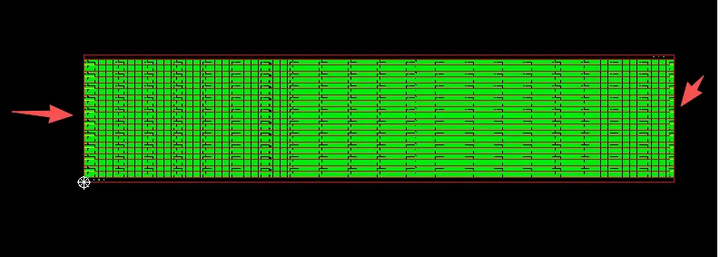
Figure 1: no panel edge protection on both sides of the board outline
The engineering recommendation was therefore twofold. First, add 5 mm waste-edge protection at each short end of the outline. These sacrificial margins provide a buffer zone that absorbs handling stress and keeps the functional edge clean after final laser forming. Second, introduce connection points along the long edges so that the continuous panel can be shipped as a single unit without intermediate break points until the customer performs the final separation. The combination of 5 mm waste edges and connection points converts an unprotected long strip into a mechanically stable manufacturing unit that can travel through the plating, coverlay lamination, and laser-forming processes with minimal risk of edge damage.
| Feature | Original Data | CAM Recommendation / Approved | Primary Benefit |
|---|---|---|---|
| Short-end protection | None | 5 mm waste edge each end | Absorbs handling stress, protects functional edge |
| Long-edge continuity | No connection points | Connection tabs added | Enables continuous-panel shipment and handling |
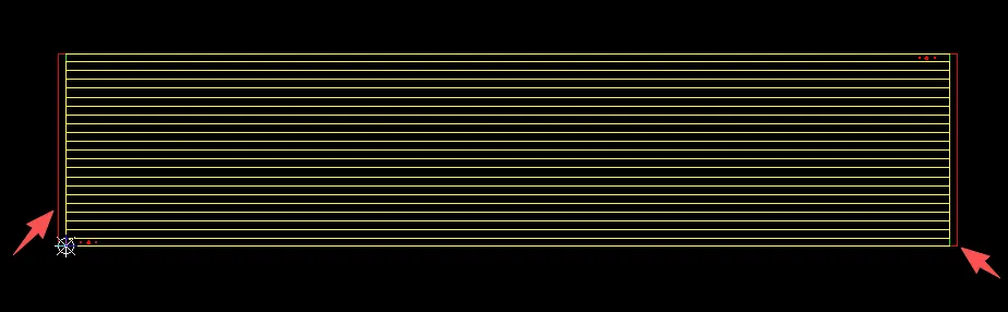
Figure 2: adding 5 mm waste rails on both sides for edge protection
Customer confirmation of the 5 mm waste-edge addition locked the outline geometry. Once approved, the laser-forming program and V-cut paths could be updated in a single revision, eliminating a potential source of first-article delay. The same margins also simplified fixture design for the flying-probe test, because the protected ends could be used as non-functional clamping zones.
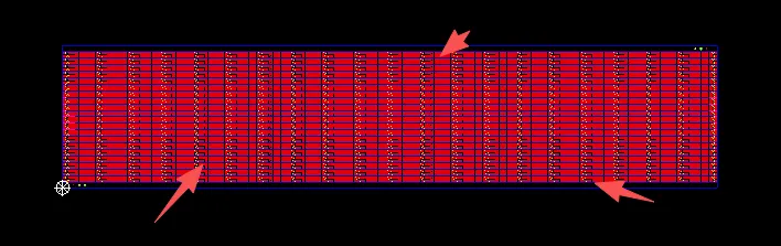
Figure 3: adding connection tabs for panelization
Adjusting Finished Thickness for White Coverlay Build-Up
The order specified a finished thickness of 0.2 mm together with white coverlay on both sides. Each side of the white film contributes approximately 15 µm of coverlay material. When both sides are laminated, the added thickness exceeds the original 0.2 mm target. Maintaining the stated 0.2 mm would require either thinning the base polyimide below practical limits or accepting a non-compliant finished dimension.
The production package therefore proposed controlling the finished thickness at 0.23 ± 0.03 mm. This range accommodates the two coverlay layers while remaining within normal process capability for laser-formed Flexible PCBs. The adjustment was presented as a direct consequence of the coverlay build-up rather than a design change, and customer confirmation was requested before the stack-up drawing was frozen.
By locking the thickness control value early, the manufacturing package avoided later disputes over dimensional measurement and ensured that the laser-forming parameters and V-cut depth would be calculated against a realistic finished dimension.
| Parameter | Original Specification | Coverlay Contribution | Approved Control |
|---|---|---|---|
| Finished thickness | 0.2 mm | ~15 µm per side (≈30 µm total) | 0.23 ± 0.03 mm |
Enlarging Silkscreen Characters for Reliable Legibility
The supplied silkscreen data contained characters whose height was too small to be printed reliably on the white coverlay. On flexible circuits the combination of thin substrate, white coverlay surface, and black ink already places tight constraints on minimum feature size. Characters below approximately 0.8 mm height tend to fill, break, or become illegible after coverlay lamination and curing.
The engineering recommendation was to enlarge all characters to a minimum height greater than 0.8 mm. This change affects only the legend artwork and does not alter the electrical design. Once the customer confirmed that the enlarged characters still met functional requirements, the silkscreen plot was regenerated and the manufacturing package could proceed.
The character-height confirmation was treated as a production-marking readiness item. Clear, readable legends support both internal process identification and any customer requirement for permanent marking after depanelization.
The Optimization Strategy: Panel Stability and Process Efficiency
With the 5 mm waste edges, connection points, thickness control, and character height confirmed, the manufacturing package could be optimized for the long-strip format. The added waste edges provided non-functional zones that could be used for temporary tooling tabs or clamping during laser forming, reducing the risk of edge tear-out. The connection points allowed the continuous panel to be handled as a single 20 × 1 unit through plating and coverlay lamination, improving throughput compared with individual-strip processing.
Because the customer retained final depanelization responsibility, the V-cut paths were aligned with the original outline while the waste edges remained outside the functional area. This arrangement preserved the customer's intended panelization method while giving the factory a mechanically robust workpiece for the preceding process steps. The thickness control value of 0.23 ± 0.03 mm was entered into the laser-forming program so that cut depth and energy settings matched the actual finished dimension, avoiding incomplete cuts or excessive heat-affected zones.
The resulting manufacturing package—updated outline with 5 mm waste edges and connection points, revised stack-up drawing, and enlarged silkscreen—required no further engineering clarification once customer confirmation was received. Production could proceed on the original 14-day schedule.
Production Readiness Checklist
Before the manufacturing files were released, the following items were verified against the resolved engineering questions:
- 5 mm waste-edge protection added at both short ends of the 600 mm outline.
- Connection points introduced to support continuous-panel shipment.
- Finished thickness control revised to 0.23 ± 0.03 mm to accommodate dual-side white coverlay.
- Silkscreen character height increased above 0.8 mm and plot regenerated.
- Laser-forming and V-cut programs updated to the new outline and thickness.
- Final manufacturing package cross-checked against original customer data and released for production.
| Item | Action Completed | Purpose |
|---|---|---|
| Waste-edge protection | 5 mm added at both short ends | Prevent handling and plating damage |
| Connection points | Tabs introduced for continuous panel | Enable stable continuous shipment |
| Finished thickness | Set to 0.23 ± 0.03 mm | Accommodate dual-side white coverlay |
| Silkscreen height | Characters enlarged >0.8 mm | Ensure legible permanent marking |
| Process programs | Laser and V-cut updated | Match new outline and thickness |
Final Production Outcome
The engineering preparation converted an unprotected 600 mm flexible strip into a production-ready continuous panel. The 5 mm waste edges at both ends provided the mechanical buffer required for safe handling and plating, while the connection points enabled efficient continuous shipment. The thickness adjustment of 0.23 ± 0.03 mm reconciled the dual-side white coverlay with a realistic finished dimension. Enlarged silkscreen characters ensured legible permanent marking. Together these steps eliminated the primary sources of first-article delay that commonly accompany long, thin FPCs—edge damage, thickness non-conformance, and illegible legends—allowing the job to move directly into the 14-day production window.
FAQ
Q1: Why is 5 mm waste-edge protection recommended on a long FPC when the original design has none?
A1: Unprotected ends on a 600 mm flexible strip are easily damaged during handling, plating transport, and packaging. The 5 mm sacrificial margins absorb mechanical stress and keep the functional edge intact after laser forming.
Q2: Why cannot a 0.2 mm finished thickness be maintained when white coverlay is applied on both sides?
A2: Each white coverlay layer contributes approximately 15 µm. Dual-side application exceeds the original 0.2 mm target. Controlling finished thickness at 0.23 ± 0.03 mm accommodates the coverlay build-up while remaining within normal process capability.
Q3: What is the purpose of adding connection points for continuous-panel shipment?
A3: Connection points keep the long strip as a single continuous unit through plating and coverlay lamination, reducing handling damage and improving process efficiency until the customer performs final separation.
Q4: Why must silkscreen characters on an FPC be enlarged above 0.8 mm height?
A4: Characters smaller than approximately 0.8 mm tend to fill, break, or become illegible after coverlay lamination and curing on a thin flexible substrate. Enlarging them ensures reliable permanent marking.
Q5: How does proper FPC edge protection improve manufacturing efficiency?
A5: Protected ends reduce edge-related scrap, allow safer clamping during laser forming, and support continuous-panel handling. The net result is higher first-pass yield and more predictable lead time on long flexible circuits.
Q6: Can a long FPC be produced without any waste edge if the customer accepts the risk?
A6: It is technically possible, but the unprotected ends significantly increase the probability of handling damage, plating-edge defects, and shipping rejects. Adding a modest waste edge is the practical method for maintaining both quality and throughput.