 00:59
00:59
Bend Radius
Bend radius is a critical parameter in the design and manufacturing of flexible printed circuit boards (PCBs), cables, and electronic assemblies, defining the minimum curvature a material can withstand without risking damage such as cracking, delamination, or signal degradation. For engineers and designers searching for information on bend radius, this tag serves as a comprehensive resource, gathering insights into its role in ensuring the reliability and performance of flexible electronics. Understanding bend radius helps prevent common failures in applications like wearable devices, automotive sensors, and medical equipment, where repeated flexing or tight installations are common. In practical terms, calculating the appropriate bend radius involves factors such as material thickness, copper trace width, and environmental conditions. For instance, in flex PCBs, a general rule of thumb is to maintain a bend radius at least 10 times the board's thickness for single-layer designs, though this can vary based on multilayer configurations or high-frequency requirements. Adhering to standards like IPC-2223 provides guidelines to optimize designs, reducing stress on components and extending product lifespan. Designers can apply these principles to select suitable materials, such as polyimide substrates, and incorporate strain relief features to accommodate dynamic movements. This collection of articles under the bend radius tag offers detailed explorations of these concepts, including step-by-step calculation methods, case studies from real-world implementations, and comparisons of bending techniques for rigid-flex hybrids. By reviewing these resources, you can refine your approach to flexible circuit design, troubleshoot potential issues early, and integrate best practices that align with industry benchmarks. Whether you are prototyping a new device or scaling production, the knowledge here equips you to make informed decisions that enhance durability and functionality.
Video Guide
-
00:59
Technical Articles
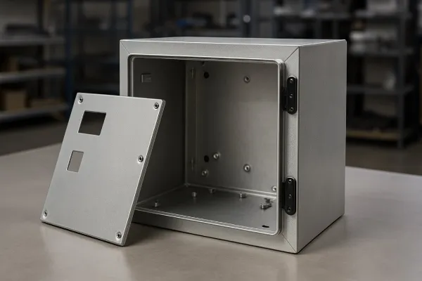
Common Sheet Metal Design Mistakes for PCB Enclosures
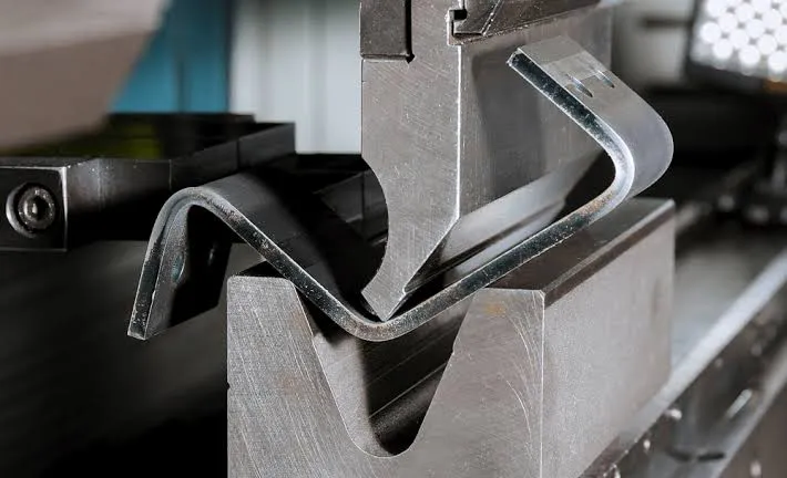
Sheet Metal Prototype Manufacturing Process Explained
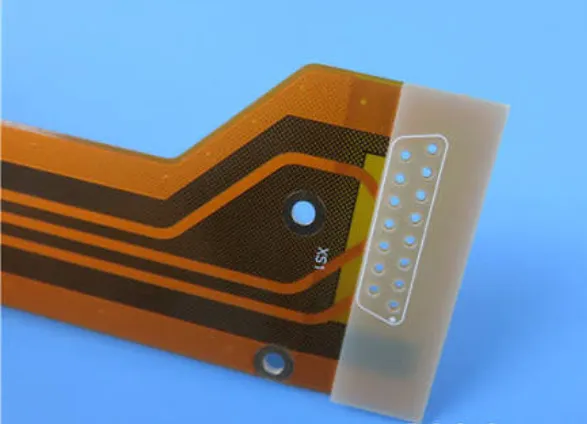
PI Stiffener vs FR4 Stiffener – Which One Should You Use?
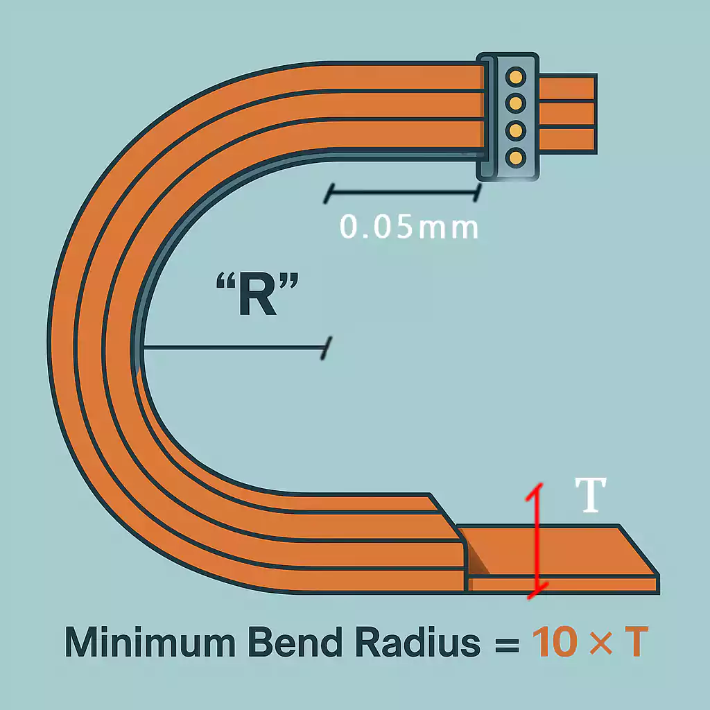
Can Flexible PCB Be Folded 180 Degrees? A Guide to Folding FPC
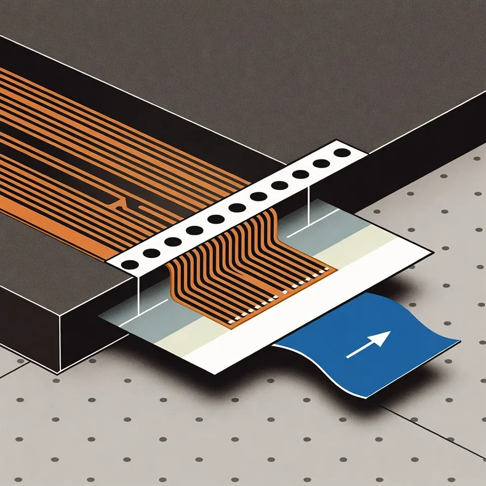
Best Way to Design Glue Paper Pull-out on FPC Panels
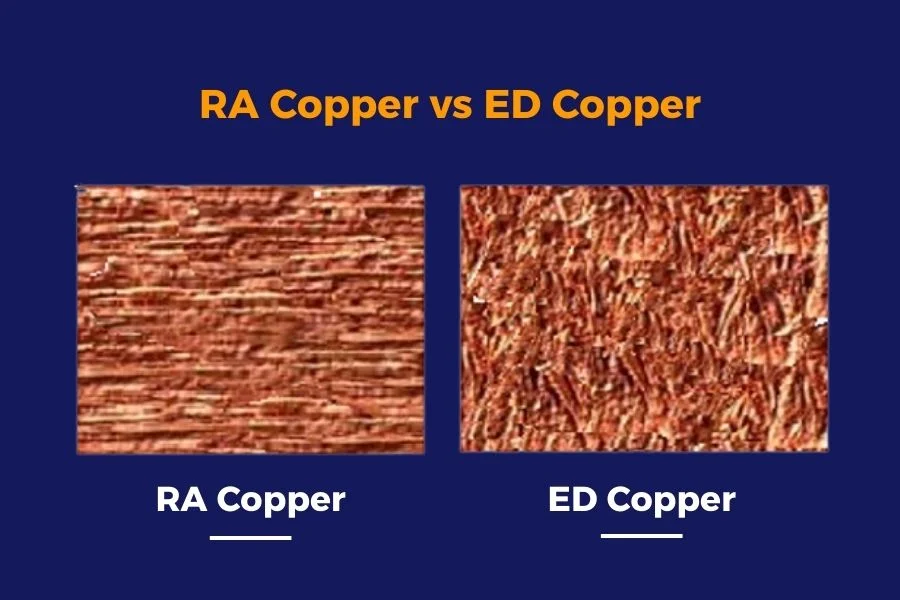
RA Copper vs ED Copper for Flexible PCB
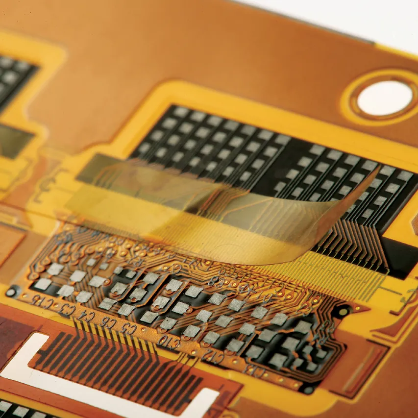
FPC Tape: Why Flush Edges Cause Adhesive Overflow
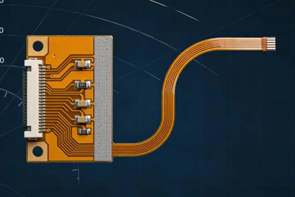
How Much Clearance Between FPC Trace and Board Edge Is Safe?
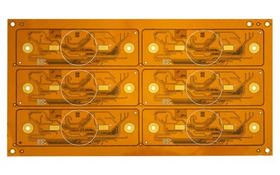
How to Properly Specify Back Adhesive Type and Thickness for FPC
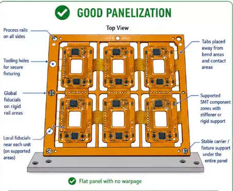
When Should You Add Waste Edge Protection on FPC Panels?
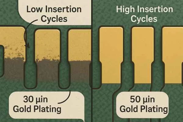
What Total Thickness Should You Control for FPC Insertion Finger Area?
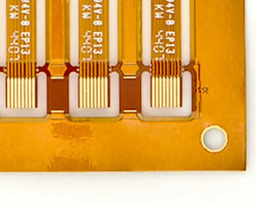
How Many Connection Points Are Needed for Stable FPC Panel Shipment?
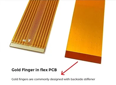
How Far Should PI Stiffener Be from FPC Gold Finger Opening?
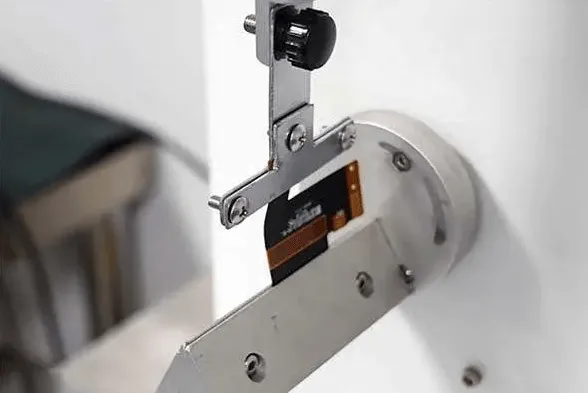
Constraint Management Techniques for Flexible and Rigid Flex PCBs
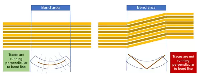
Flexible HDI PCB Design for Flex and Rigid-Flex Applications
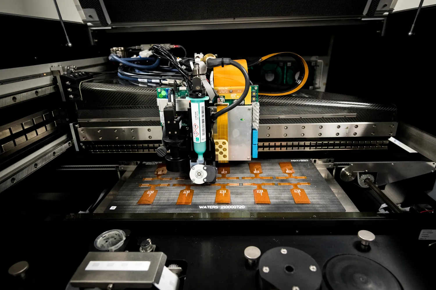
Implementing DFA in Flex and Rigid Flex PCB Design
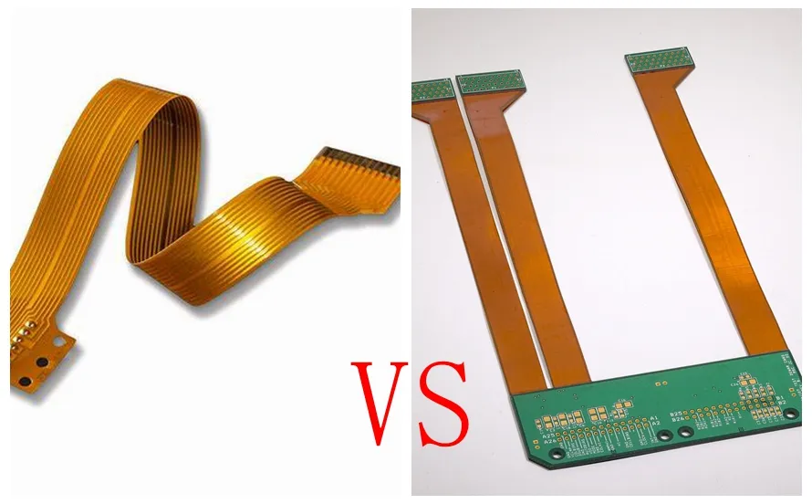
Overcoming Common Flex and Flex Rigid Design Challenges in PCB Design
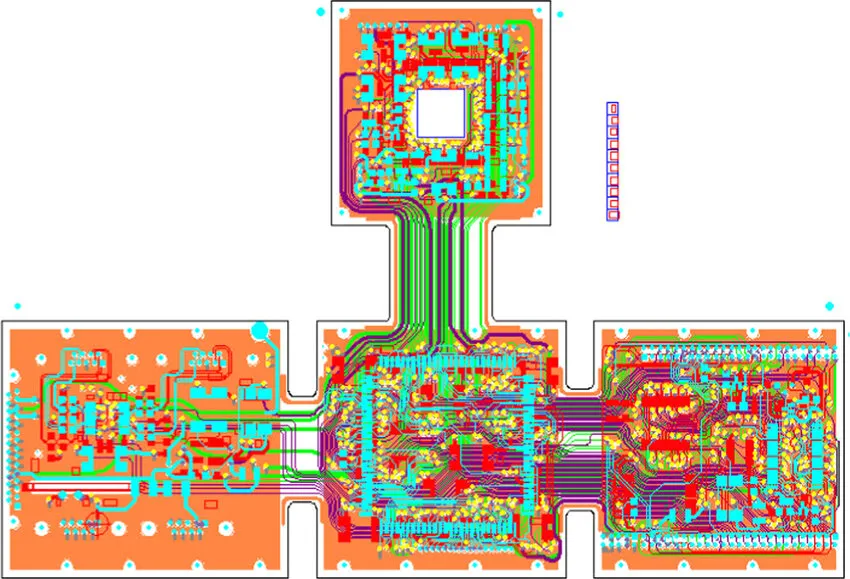
Designing Flex and Rigid-Flex PCBs: A Comprehensive Manufacturing Guide
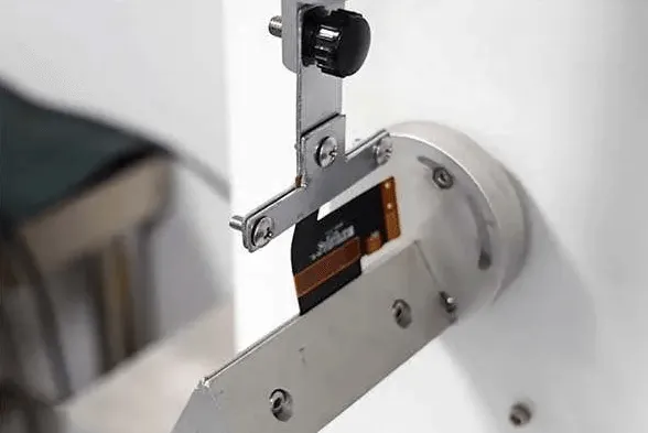
Core Thickness and PCB Flexibility: Designing Circuits That Bend Without Breaking