 02:22
02:22
PCB Panelization
PCB panelization is a critical process in printed circuit board manufacturing that involves arranging multiple individual PCBs onto a single larger panel for efficient production. This technique streamlines assembly, reduces material waste, and lowers overall costs, making it essential for high-volume runs or complex designs. By grouping boards together, manufacturers can optimize handling during fabrication, soldering, and testing phases, which is particularly beneficial for prototypes transitioning to mass production. For engineers and designers searching for PCB panelization strategies, understanding this method helps avoid common pitfalls like misalignment or depaneling issues that could compromise board integrity. Key aspects of PCB panelization include selecting the right method, such as tab routing for easy separation or V-scoring for clean breaks without additional tools. Best practices emphasize incorporating fiducials for precise alignment, maintaining adequate spacing to prevent thermal stress, and considering panel borders to accommodate automated machinery. These elements ensure higher yields and faster turnaround times, directly addressing the needs of professionals aiming to enhance scalability in electronics projects. Whether you are dealing with rigid, flexible, or multilayer boards, proper panelization can significantly improve reliability and reduce defects. Our articles delve into real-world applications, from automotive electronics to consumer gadgets, offering practical tips on software tools for panel design and troubleshooting common errors. Browsing through these resources provides in-depth guidance on integrating panelization into your workflow, helping you achieve optimal results in your next PCB project.
Video Guide
Technical Articles
Choosing the Right PCB Depaneling Method: A Comprehensive Comparison
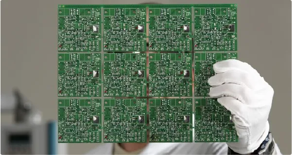
Laser Direct Imaging Accurately Images PCB Panels
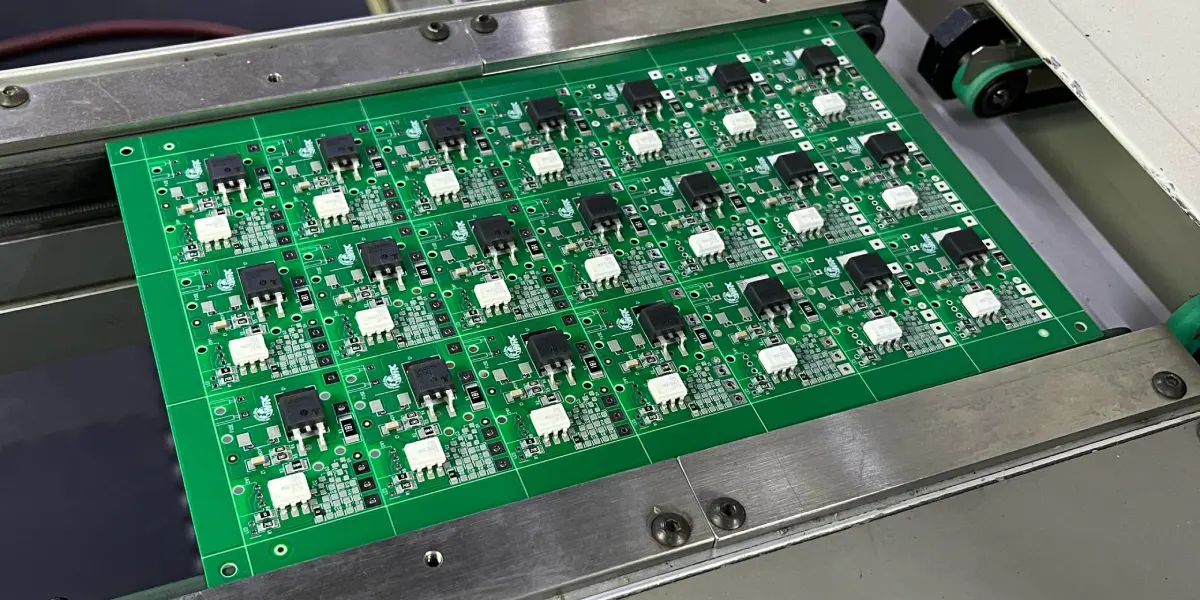
The Ultimate Guide to Depaneling Machines: Types, Features, and Applications
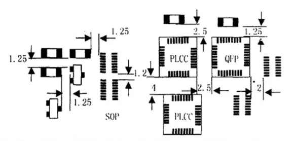
Designing for Automation: Key Principles for Efficient PCB Assembly Lines
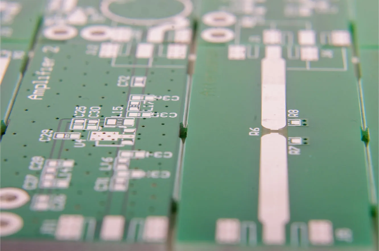
Cracking the Code: Optimizing V Scoring for PCB Depaneling Success
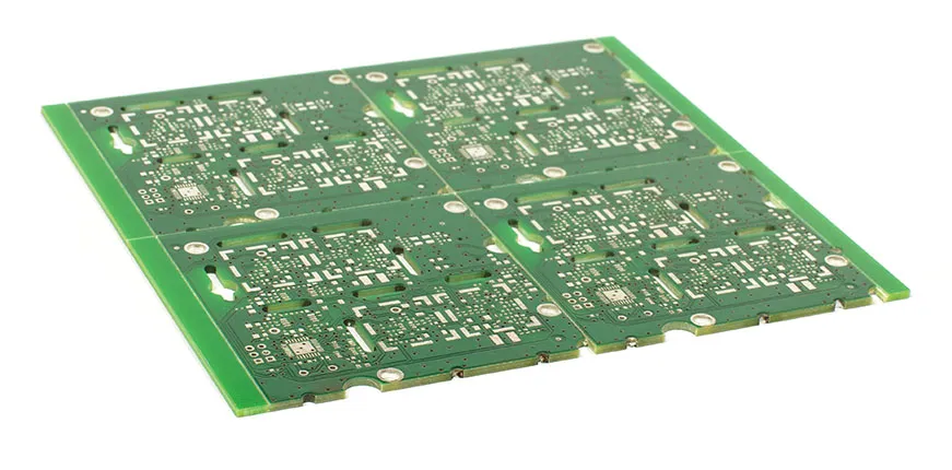
Mastering PCB Depaneling: A Step by Step Tutorial
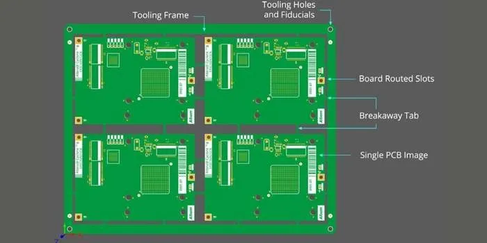
Panel Design for Manufacturing: A Comprehensive Overview
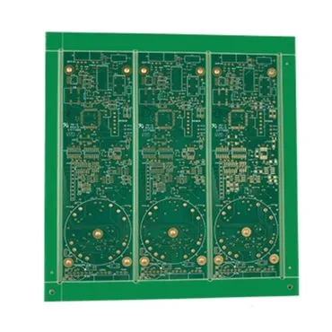
Optimizing PCB Design: V-Scoring, Component Placement, and Reliability
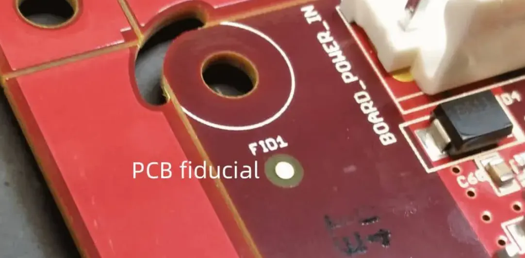
Panelization: SMT alignment
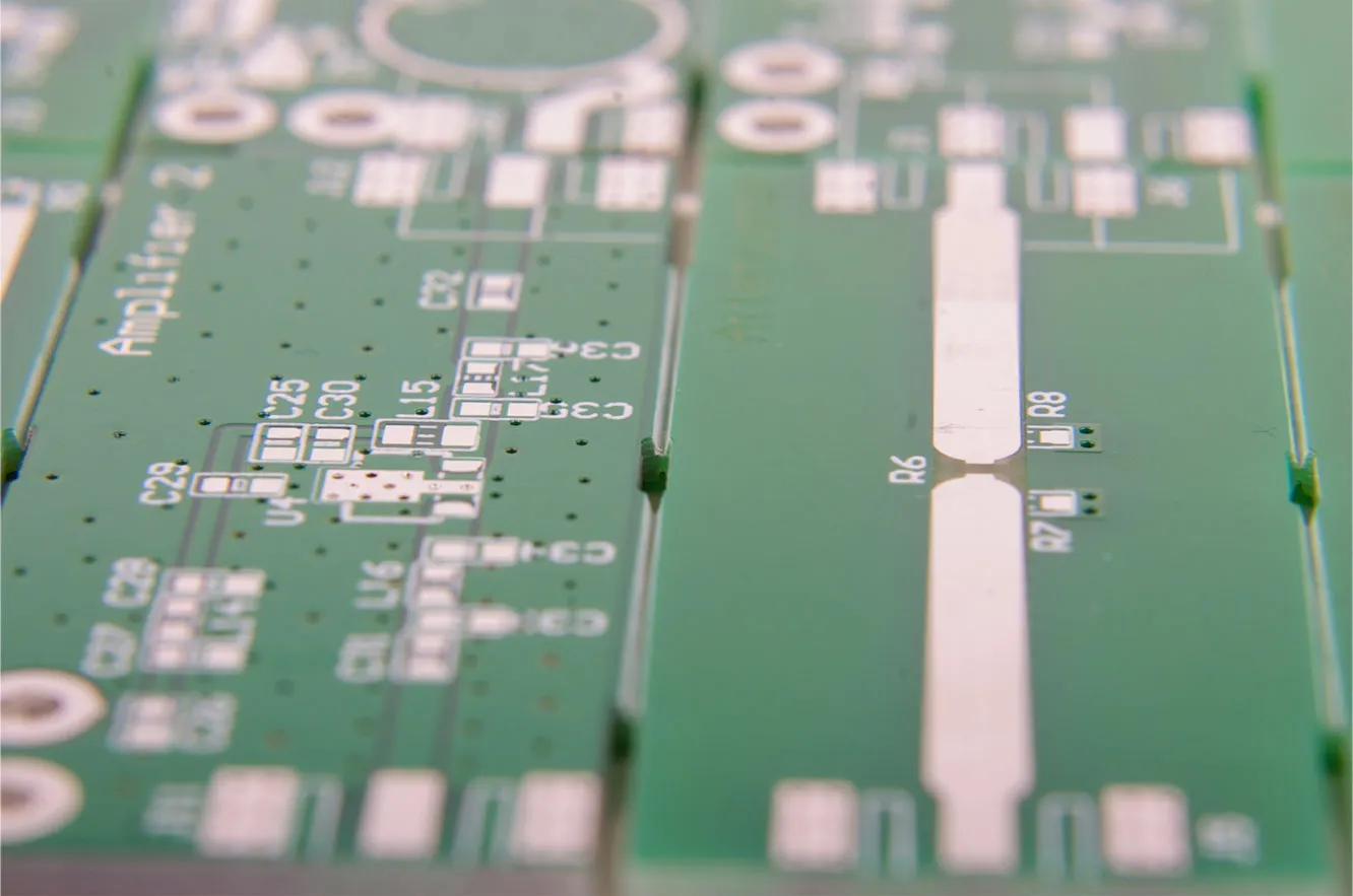
Depanelization Demystified: Mouse Bites vs. V-Score in PCB Manufacturing
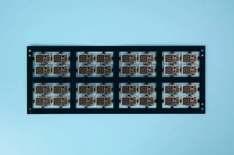
V-Scoring vs. Stamp Hole: Which PCB Depaneling Method is Right for You?
Troubleshooting PCB Panelization: Common Problems and Expert Solutions
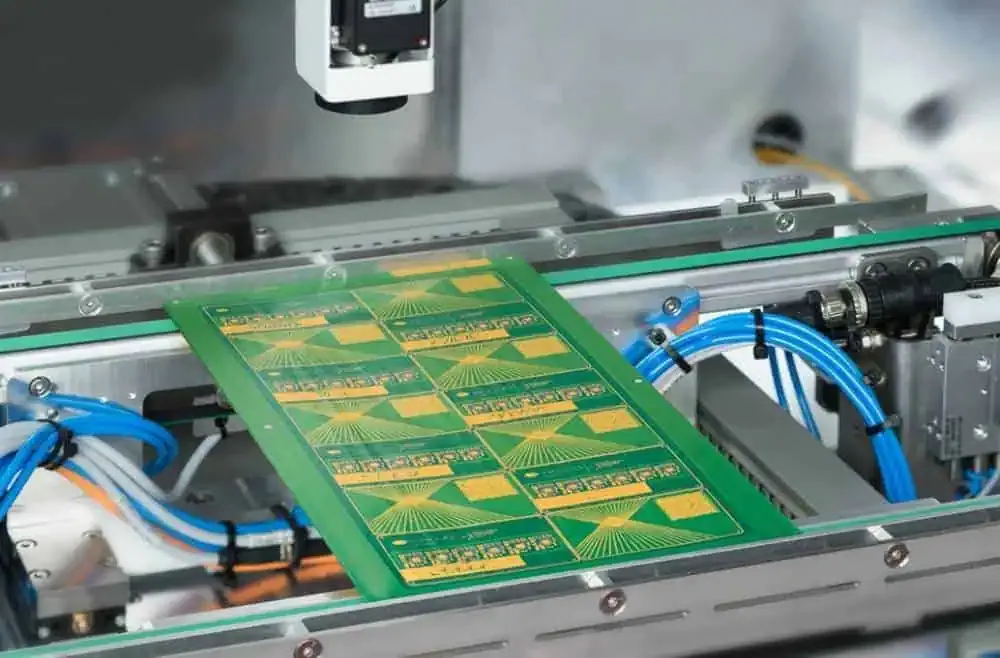
How Tab Routing Optimizes PCB Assembly: A Comprehensive Guide
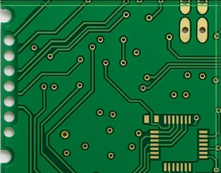
Mastering Mouse Bites: A Comprehensive Guide to PCB Panelization
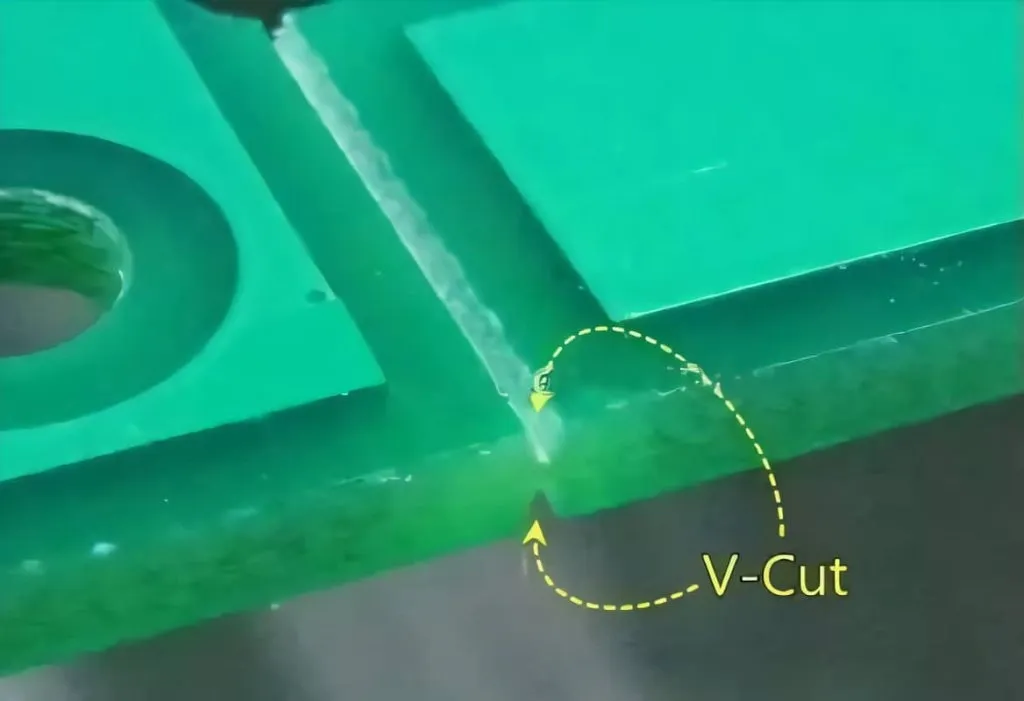
Making the Cut: Choosing the right PCB depaneling Method
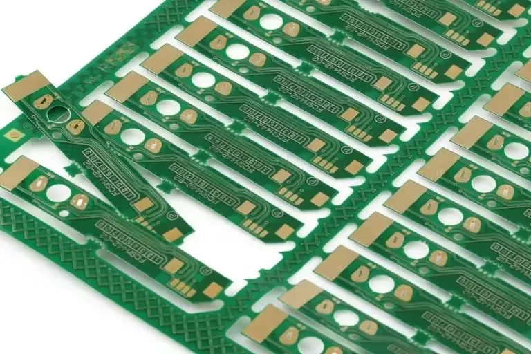
PCB Panel Size Calculation: Enhancing Manufacturing Efficiency and Reducing Material Waste
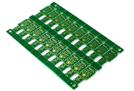
V-Scoring vs. Routing: Selecting the Optimal PCB Depaneling Method
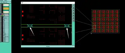
Real Panelization, V-Cut and Edge Clearance Issues from Production
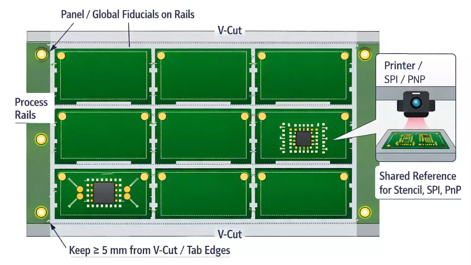
FR4 PCB Panelization Design: Fiducials, Rails, and Tooling Holes