Once a job is released for panel production, the PCB edge rails still have to be settled before that working panel can go to the floor. CAM needs to see whether a rail exists, which sides carry it, what has been placed on it, and whether the factory is asking to change any of that construction. Unit count in the note rarely answers those points on its own. Those edge rails — the process edge, tooling rail, or breakaway rail — are the scrap strip used for gripping, marking, plating balance, packing, and later discard.
The rest of this article stays on that rail: who defined it, whether it exists on each side, and which factory changes to rails, array, corners, or copper need a revised panel document. V-score depth, SMT fixtures, and factory rail defaults belong to other reviews.
| Released condition | What CAM sees | What is not decided |
|---|---|---|
| Order or drawing asks for a panel; factory sends a sketch with rails, fiducials, and tooling holes | Two panel definitions in one job | Which drawing is the manufacturing panel |
| Customer array has no process edge on both ends | Outline or panel drawing uses the product edge as the panel edge | Whether SMT or handling may use that panel as drawn |
| Customer array (EQ example: 1×3) versus factory re-array (EQ example: 3×2) plus stamp-hole singulation | Unit count, panel size, and scrap-rail area disagree | Whether array and singulation may change |
| Process edges drawn with square corners | External corners of the rail are right angles | Whether those corners may be changed for handling, film, or bag risk |
| Factory asks to pour copper on the process edge | Rail copper is not in the customer panel or outline copper | Whether scrap-rail copper is allowed |
Those five conditions are the same review seen in different files. Sometimes the rail is missing. Sometimes it exists on only some sides. Sometimes the corners or copper on it are not what the factory will run. Sometimes the factory wants a different array around it.
PCB Edge Rails: Panel Notes vs. Released Panel Geometry
The package often carries two instructions that look like one. The order or fabrication note calls for PCB panelization in production, while the geometry that arrives with that note — customer panel drawing, Gerber outline, and sometimes already-panelized outer copper — may show no rail, a rail on only some sides, or a rail that does not match the sketch attached to the EQ.
Each source answers a different part of the job. A note can say "panelize" and even call an array such as 1×3. If a customer panel drawing is in the package, that drawing is what CAM treats as the manufacturing panel, because it shows unit placement, process-edge presence, corners, and any marks already on the scrap. The Gerber outline is the contour CAM will follow until a later drawing replaces it. Which sides have edge rails, how wide those rails are drawn, how the external corners are treated, whether copper sits on the rail, and whether fiducials or tooling holes are present all have to be read from that geometry; the word "panel" in the note does not supply them.
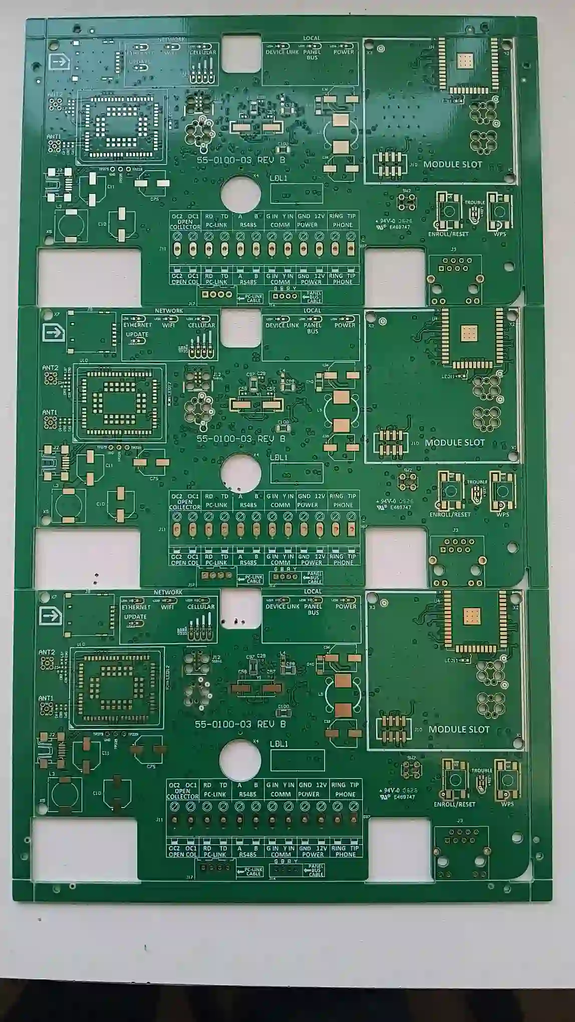
When the factory attaches a "conventional" sketch, CAM is looking at a second panel definition. In one EQ the factory sends a drawing with process edges on two sides and, in their wording, "optical points" and locating holes on those rails, including a proposed "4 mm" rail on that sketch. Confirming the sketch accepts that construction for the job. The "4 mm" figure belongs to that proposal and should not be copied onto other jobs as an edge-rail requirement.
A single-board outline with no rails and a working panel with breakaway rails have to be treated as separate objects, and the same is true of array count versus process-edge construction. The first CAM check is to establish which panel definition is actually released. From there, CAM can verify which sides have a process edge and what has been added to those rails. A missing rail stays missing until the customer accepts a revised panel drawing.
PCB Edge Rail Requirements: What CAM Can Confirm from the Files
Once that released panel is named, the files can be overlaid: customer panel drawing against Gerber outline, order array text against both, and the factory sketch against all three when the EQ attached one.
That overlay is useful for geometry. It can show unit count and orientation, whether a strip exists outside the unit outline on each side, the drawn rail width on the sketch under review, square versus already-radiused external corners, copper on the rail or empty copper, fiducial flashes and tooling-hole hits on that rail, and stamp-hole locations if they are drawn.
It cannot settle the process claims sitting behind the EQ. SMT scatter, dry-film or bag puncture, plating or warpage "need" for rail copper, commercial acceptance of a new array, and whether factory-standard marks match the assembler all need a yes or no on a specific change.
Panel size text in the note is checked against the drawing it belongs to. One EQ states the customer data as a 1×3 at 12.4 × 7 cm and the factory proposal as 3×2 at 114 × 94 mm. Each size is read with its own drawing, and neither figure redesigns the panel by itself.
| Compared objects | Measures | Does not measure |
|---|---|---|
| Outline versus customer panel drawing | Rail present on N/S/E/W; drawn width on that file; corners | SMT grip, scatter risk |
| Panel drawing versus order array text | Unit count; panel X/Y as drawn | Whether waste justifies a new array |
| Outer copper versus rail outline | Copper on the process edge or not | Plating uniformity or warpage |
| Rail area versus silk or copper marks | Fiducials and tooling holes drawn or not | Assembler fiducial scheme |
| Rail external corners | Square versus already broken | Dry-film or bag puncture as a fact |
PCB Tooling Edge Rails: Missing Rails and Factory-Added Rails
The question in this population is whether PCB edge rails are already part of the released panel, or whether the factory is adding a tooling rail — and the marks on it — that the package never drew.
In one common case the customer panel uses the product edge as the panel edge on both ends. The factory EQ raises a handling concern: with no process edge on those two sides, the panel is easy to scatter and poor for SMT. That concern can be genuine, but adding the rail still waits on a revised panel document. If the released drawing never gave a rail the assembler can grip, the customer either keeps the panel as drawn or accepts a named factory panel drawing.
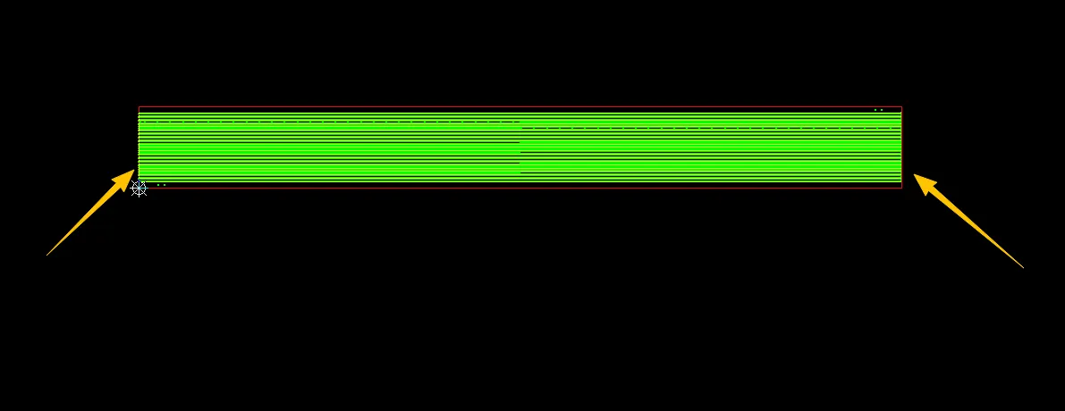
The board panelization lacks edge rails at both ends, based on our production experience, this easily leads to panel breakage, which is detrimental to SMT.
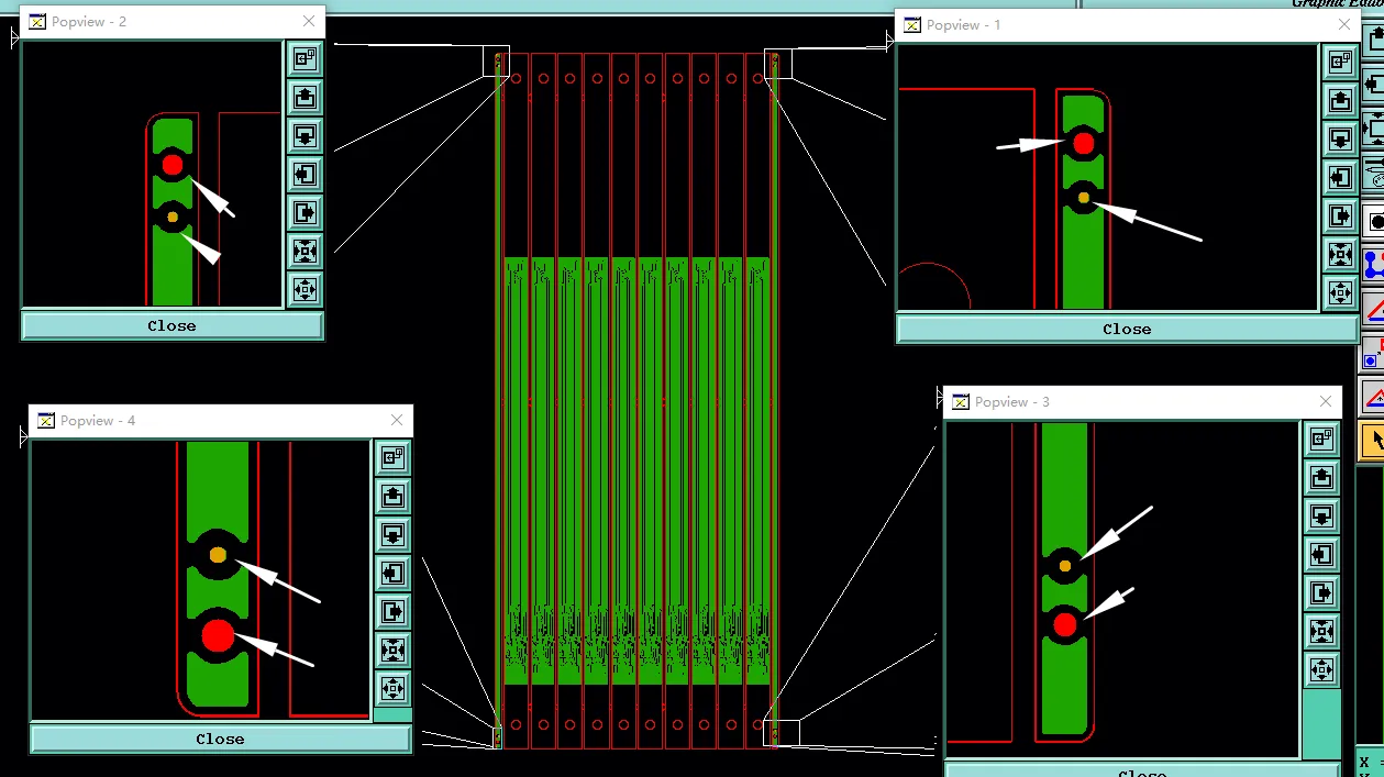
In the other case the factory sketch adds process edges plus fiducials and tooling holes "per convention." The EQ asks the customer to confirm that drawing as a whole — which sides get a rail, what sits on the rail, and that those hits stay on scrap. Fiducials on the process edge and tooling holes on the process edge are rail features and have to be drawn or called out. A tooling hole on the rail is scrap tooling and is read separately from a PTH or component hole.
"Top and bottom only" versus rails on all four sides is already a drawn choice, so both the customer file and the factory sketch need to be read for which sides actually carry a rail during panelization confirmation. If a width appears, it is the width on the sketch under review — here, the factory's "4 mm" wording on their own drawing.

Our standard panel layout with 4mm process edges top and bottom.
PCB Edge Rails for SMT: When the Factory Proposes a Different Panel
The rail may already exist in this case. What the factory wants to change is the working panel around it, because of process-edge scrap on the released array.
The EQ is tied to that array. Customer data calls a 1×3 at the stated size; the factory says that panel leaves too much process-edge waste and proposes a 3×2 at a different panel size with stamp-hole singulation. Re-array moves more than scrap. It also moves panel outline, rail length and location, where fiducials and tooling holes can sit, and how units separate. Stamp-hole (mouse-bite) singulation travels with that proposal and should not be assumed for every process-edge job.
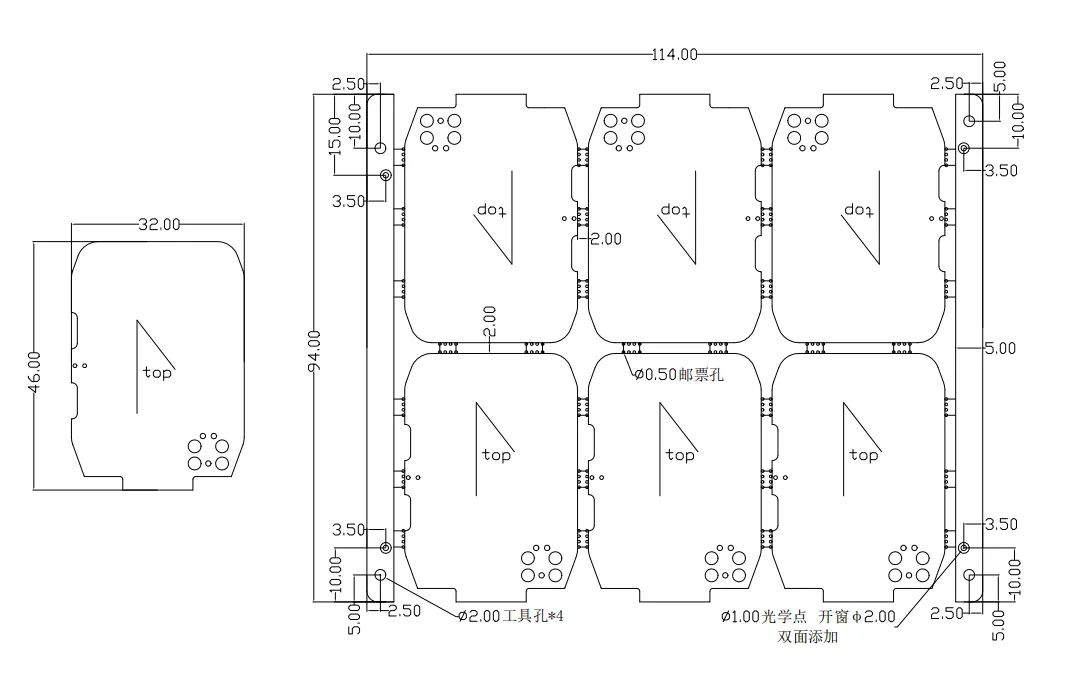
3x2 panel, dimensions 114*94mm, final depaneling via stamp holes.
Scrap-rail area can be measured on both drawings, but that measurement does not replace the released array on its own. The finished unit outline stays the customer unit. Re-array revises the panel document; the board outline of each unit stays put. If the customer already supplied a panel drawing, the factory 3×2 sketch is a second panel definition, in the same class as an added rail.
Unit count, rotation, panel X/Y, and rail placement can be compared directly, and proposed stamp holes should sit on the rail or tab, clear of any unit keep-out already drawn. Whether the order's array text is mandatory or only a suggestion comes from the package wording.
PCB Edge Rail Design: Corners, Copper, and Rail Geometry
By this point the rail exists, or it will exist after the first two questions close. The factory then wants the scrap rail to differ from the released drawing — external corners, copper, or both — so CAM has to confirm whether the process edge on the manufacturing panel may differ from the process edge the customer drew.
Right-Angle Corners on the Process Edge
The customer panel drawing shows process edges with square external corners. The factory EQ says those right angles can puncture dry film and packaging bags in transport and fabrication.
PCB edge corner treatment belongs to rail geometry, so changing it changes the panel outline CAM will mill, score, and ship. The unit outline stays as drawn unless that square corner is actually the unit corner, which has to be checked first. No radius is invented for the close. The ask is whether the external corners of the rail may be broken or radiused on the manufacturing panel drawing.
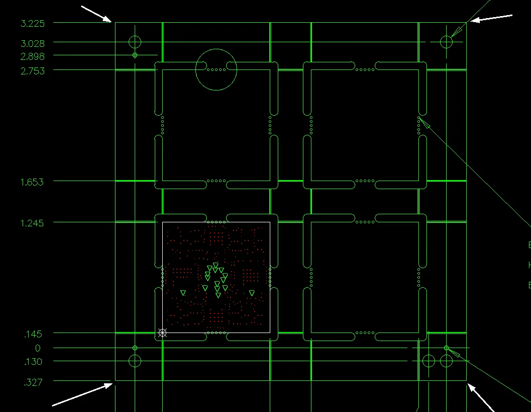
Process edges had sharp corners.
If any corner is already broken on the Gerber outline but square on the PDF panel sketch, that mismatch should be recorded. A corner change then closes as a revised panel outline, leaving the unit contour off that edit.
Copper Pour on the Process Edge
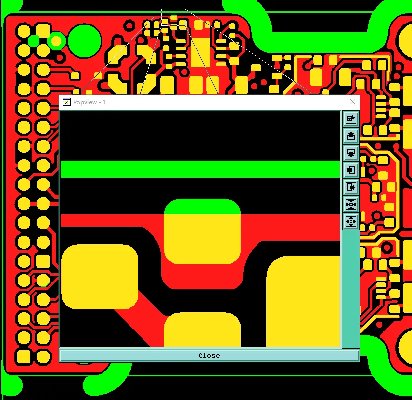
A separate EQ asks to pour copper on the process edge for plating quality and warpage control.
That copper lives on scrap, yet it still changes the released outer-layer image on the working panel: plating area, balance, and what is visible on the rail in process. An empty customer rail is the released copper condition. "Improve plating / warpage" is the reason for the ask; the pour still needs confirmation.
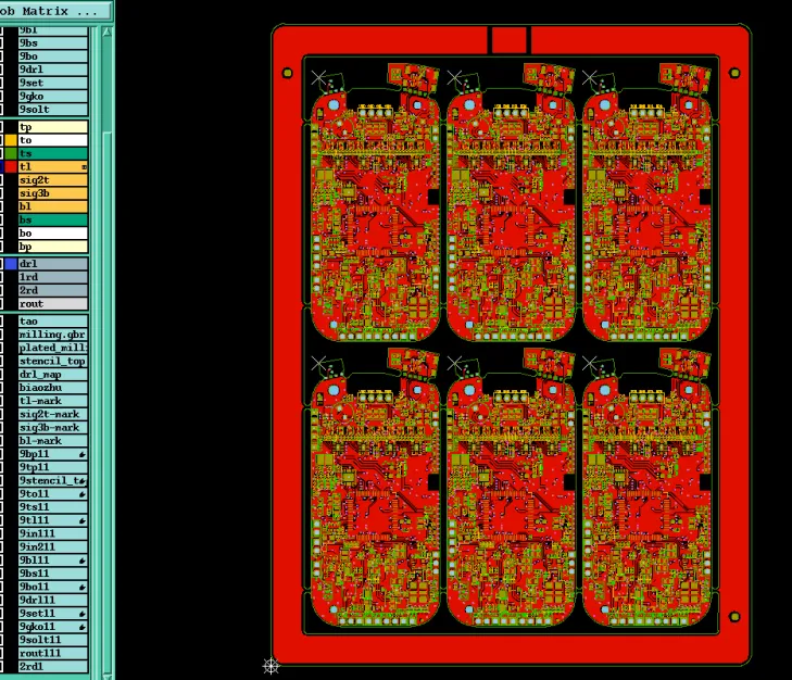
copper pour on the process edges
Rail copper and rail marks can be decided separately. A bare rail can carry fiducials and tooling holes, and a poured rail still needs those marks called out if they are required. Density or thieving rules are outside this close. What needs confirming is whether scrap-rail copper is allowed, and on which layers if the package names them.
Customer outer copper is compared with the rail outline to see whether the pour is present, partial, or empty. Accepted copper stays on the rail and leaves solder-mask and paste features on the unit alone.
PCB Edge Rail Changes: How CAM Closes the Manufacturing Panel
The EQ closes on an explicit manufacturing document. House convention waits on that document. Any of the three paths can be the close; none arrives pre-selected.
| Path | What gets released | What stays locked |
|---|---|---|
| Keep the released panel | Customer array, rail presence or absence, corners, and rail copper as drawn | Factory leaves rails, fiducials, tooling holes, array, corners, and rail copper as released |
| Accept the factory panel drawing | Named sketch becomes the working panel: rails, marks on the rail, and/or new array plus stamp-hole singulation, and/or the corner or copper changes listed on that sketch | Finished unit outline and product copper inside the unit |
| Split close | Example: allow rails plus fiducials plus tooling holes for handling, and keep the customer array; or allow a corner break on scrap only; or allow rail copper only | Each allowed change written; anything off that list stays as released |
The answer sets how the working panel is built and handled — plating, dry film, packing, SMT rail — how the units stay together, and how they are singulated. The circuit on the unit stays as released.
A usable close names the construction that will actually run: which sides have edge rails; whether fiducials and tooling holes on those rails are accepted; array and panel size if those change; singulation if stamp holes are on the proposal; corner treatment; and copper on the rail, including layers if they were stated. A confirmed factory sketch can then be stored as the panel document for the job.
Before release it should be clear which file owns the panel, which sides have a rail as drawn, whether fiducials and tooling holes sit on that rail, how array count and panel size in the note compare with the drawing, how the external corners of the rail are treated, whether copper is allowed on the rail, and how the panel will be singulated if it is not a single unit.
FAQ
Q1: Does "produce as a panel" mean the factory may add PCB edge rails?
A1: The note sets panel production. Rail sides, marks, corners, and copper come from the panel drawing or from a confirmed factory sketch. House convention stays off the released rail until that sketch is accepted.
Q2: If the customer array has no rails on both ends, can CAM add them for SMT handling?
A2: The outline alone does not add them. Missing end rails are a handling concern, and adding a tooling edge still needs a revised panel drawing that shows the rail and whatever fiducials or tooling holes will sit on it.
Q3: Are fiducials and tooling holes on the process edge implied by panelization?
A3: They are rail features and have to be drawn or called out. A tooling hole on the rail is scrap tooling, read separately from a PTH or component hole. If the factory sketch adds "optical points" and locating holes, those hits are part of the sketch under review.
Q4: Can the factory change a 1×3 to a 3×2 because the process-edge scrap is high?
A4: That change is an accepted panel-document revision. Scrap-rail area can be compared on both drawings, and the released array stays until the new sketch is accepted. Stamp-hole singulation travels with that sketch when it is drawn there.
Q5: May square corners on the process edge be radiused without touching the unit?
A5: Yes, when the square corners belong to the scrap rail and the customer accepts a revised panel outline. When the square corner is the finished unit corner, breaking it changes the product contour.
Q6: Is copper on the process edge required for plating or warpage control?
A6: The files leave that open. An empty customer rail is the released copper condition. Pour on the scrap rail is allowed after confirmation, on the layers named in that confirmation.