


 00:53
EMI Shielding
EMI shielding plays a critical role in modern electronics design, protecting sensitive components from electromagnetic interference that can disrupt performance or cause failures. In the context of PCB manufacturing and electronic systems, EMI shielding involves techniques and materials that block or attenuate unwanted electromagnetic radiation, ensuring devices operate reliably in environments filled with signals from wireless networks, power lines, and other sources. This tag, EMI Shielding, gathers articles that delve into the fundamentals of shielding strategies, from basic principles to advanced implementations, helping engineers and hobbyists address common challenges in signal integrity and compliance with standards like FCC or CE regulations. For those searching for EMI shielding solutions, understanding its practical applications is essential. In high-speed PCBs, for instance, shielding can prevent crosstalk between traces or protect against external noise in automotive electronics, medical devices, and telecommunications equipment. Best practices include selecting appropriate shielding materials such as conductive foams, metal enclosures, or copper foil tapes, and integrating them during the design phase to minimize costs and rework. Articles under this tag often highlight actionable insights, like calculating shielding effectiveness using formulas for attenuation or incorporating ground planes and vias to create effective barriers against interference. By exploring the resources here, readers can gain step-by-step guidance on testing EMI levels with tools like spectrum analyzers and implementing fixes such as ferrite beads or gasket seals. Whether you are troubleshooting interference in a prototype or optimizing a production run, these discussions provide the knowledge needed to enhance electromagnetic compatibility and achieve robust, interference-free designs.
Video Guide

Technical Articles

What Is the Purpose of a Via in a PCB?

Clock Circuit Layout and Routing for Crystals and Oscillators

Interface Circuit Layout and Routing Guide for PCB Designers
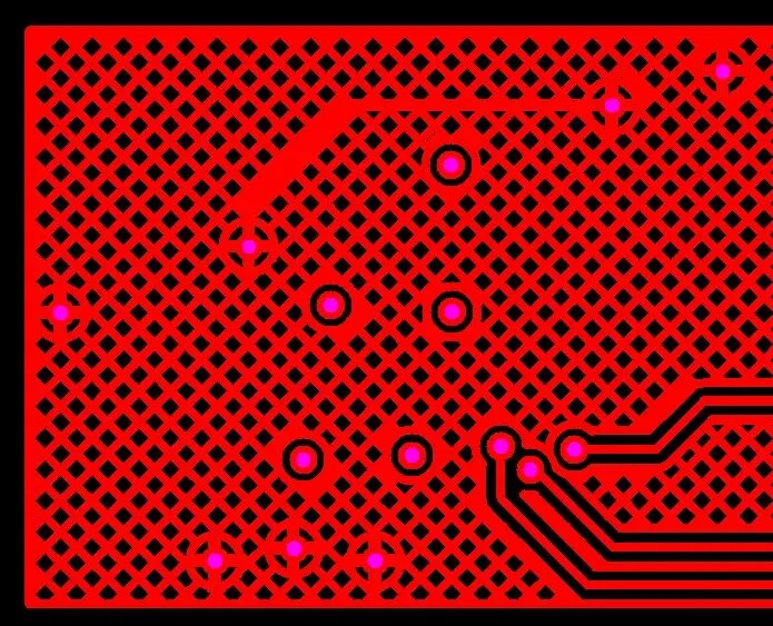
Solid Copper or Hatched Copper on PCBs and FPCs: Key Design Considerations
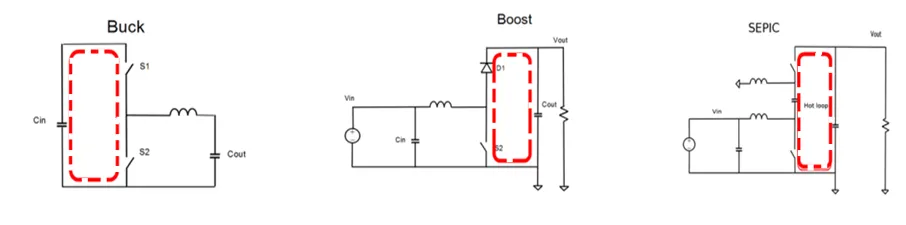
Understanding EMI in Switching Power Supplies: Why It Matters More Than PCB Rules Alone

Critical PCB Copper Pour Guidelines: When Copper Pour Can Do More Harm Than Good

4 Layer vs 6 Layer PCB: Which One Should You Choose?

6 Layer vs 8 Layer PCB: Key Differences and Cost Comparison

Key Manufacturing Technologies for Drone PCBs

EMC Design for Microcontroller Circuits: I/O, Reset, and Oscillator

Signal Interface ESD, IC Packaging, and Termination Design Guide

Board-Level EMC Design: Interference Sources, Coupling, and Immunity

Immunity Standards and RF Test Environments for PCB-Level EMC

Inductors and Diodes in EMC Design: Selection and Circuit Techniques

isoPower Radiated Emissions: Dense PCB Layout Guide
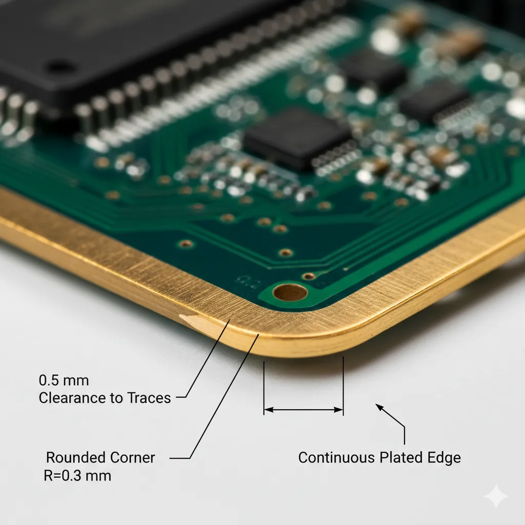
PCB Edge Plating Explained: A Guide for Electrical Engineers
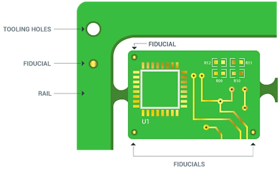
PCB Mounting Holes: Sizes, Types, Spacing & Design Guide

Grounding Concepts and Methods for PCB and Backplane Design

RF PCB Materials, Isolation and Shielding: EMC Design Guide


