High-Frequency PCB
High-frequency PCBs are essential components in modern electronics, enabling reliable performance in applications where signals operate at gigahertz levels or higher. These specialized printed circuit boards are designed to handle rapid signal transitions, minimizing issues like signal attenuation, crosstalk, and electromagnetic interference that can degrade system efficiency. Engineers and designers often turn to high-frequency PCB resources to address challenges in fields such as telecommunications, radar systems, wireless networks, and high-speed computing. Understanding the fundamentals of high-frequency PCB design starts with selecting appropriate materials, such as low-loss dielectrics like PTFE or Rogers laminates, which maintain signal integrity over extended distances. Key best practices include controlled impedance routing, where trace widths and spacing are precisely calculated to match the characteristic impedance of the transmission lines. Ground planes and via structures must be optimized to prevent unwanted resonances, while simulation tools like HFSS or CST can validate designs before prototyping. Practical applications extend to 5G infrastructure, where these PCBs support faster data rates, and in automotive radar for advanced driver-assistance systems, ensuring low latency and high reliability. For those troubleshooting common pitfalls, such as skin effect losses or parasitic capacitances, detailed guides on multilayer stackups and shielding techniques offer actionable solutions. By delving into these topics, professionals can enhance their designs to meet stringent performance standards, reducing time to market and improving overall product quality. Browsing through the articles tagged under High-Frequency PCB provides in-depth explorations of these concepts, equipping you with the knowledge to tackle real-world engineering demands effectively.
Technical Articles
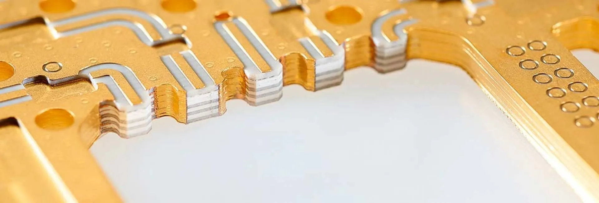
Exploring the Benefits of Multi Layer PTFE PCBs for Complex Designs
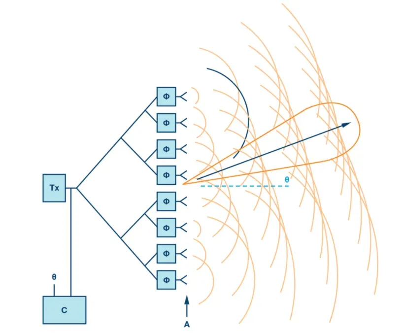
Phased-Array Antennas: Engineering Principles, Antenna Types, and RF PCB Integration

RF Front-End Growth Drivers and Market Outlook
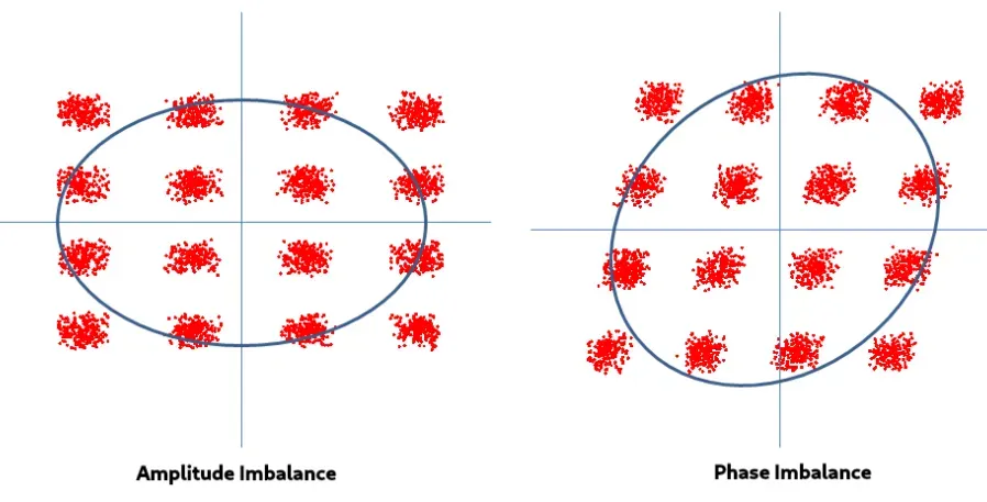
Real vs Ideal Signals in SDR-Based Simulations
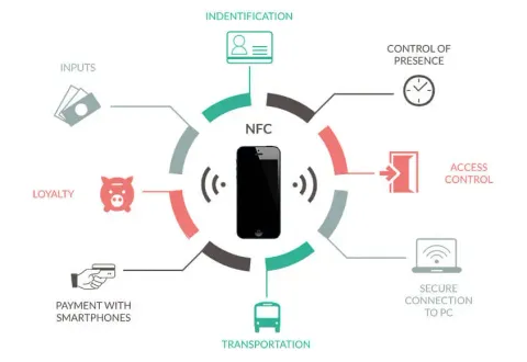
What Is NFC and Its Three Operating Modes
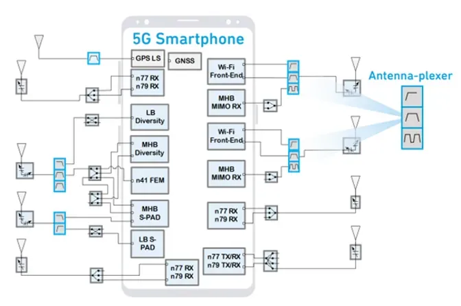
Why RF Filters Are Needed and Where They Are Used
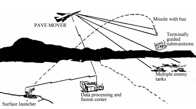
Demonstrations of LPI Radar Technologies
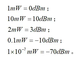
Basic Units in RF: dB, dBm, and dBW
2.4 GHz Wi-Fi: Definition, Advantages and Disadvantages
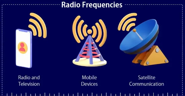
RF PCB Design Essentials: Radio Frequency Principles for High-Performance Wireless Systems
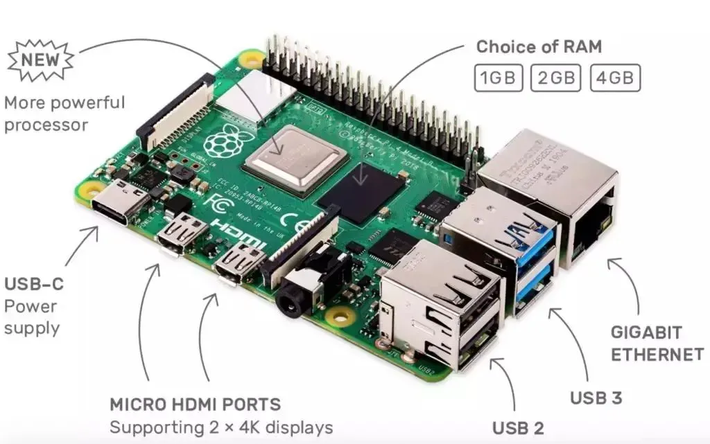
10 SDR Receiver and Transceiver Project Ideas
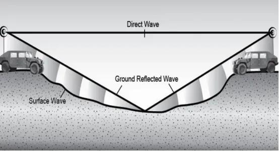
Common Multipath Propagation Paths from a Radiating Source
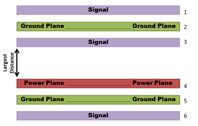
Advanced Techniques for Reducing EMI in Navigation System PCBs

WiMAX and Wi-Fi: Technical Differences
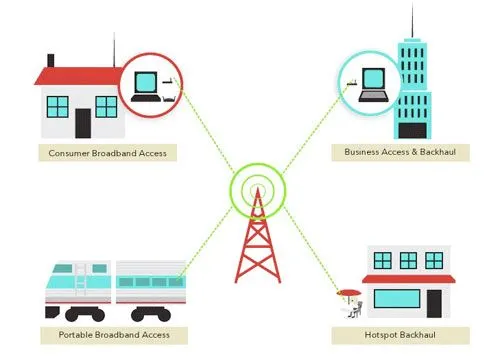
What Is WiMAX? Key Broadband Technologies
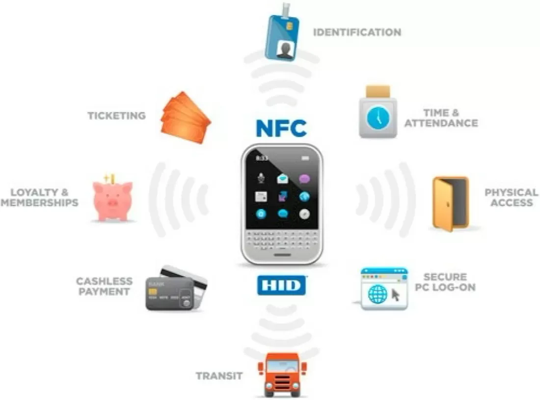
What Is NFC and Common NFC Applications
Short Range Wireless PCB Design for Bluetooth WiFi and Zigbee
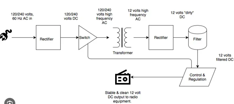
RF Power Supply Parameters and Test Principles