


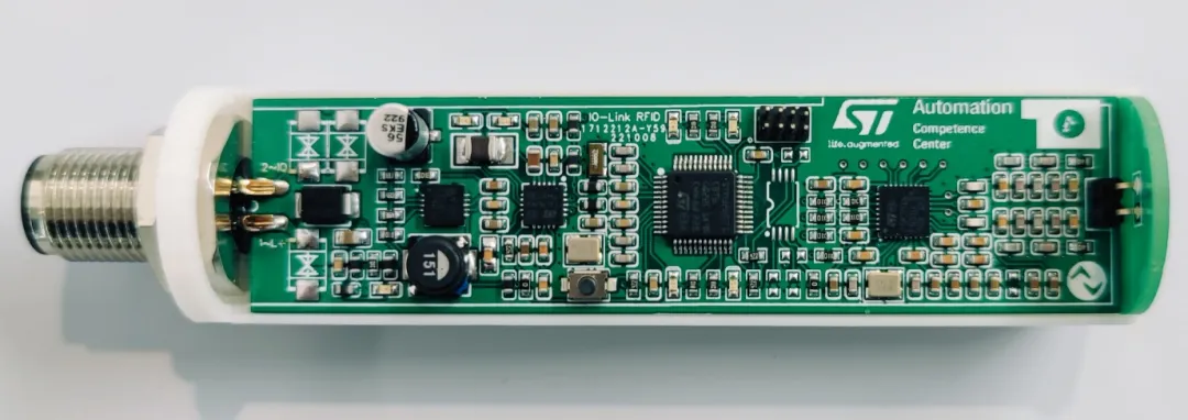
Impedance Matching
Impedance matching is a fundamental concept in electronics and PCB design that ensures optimal signal transmission and power transfer between components or systems. By aligning the impedance of a source with that of its load, engineers can minimize reflections, reduce signal distortion, and enhance overall circuit performance. This technique is particularly crucial in high-frequency applications, such as RF circuits, telecommunications, and high-speed digital systems, where mismatches can lead to significant energy loss or data errors. For professionals and hobbyists searching for impedance matching resources, this tag page serves as a centralized hub for articles that delve into practical strategies and real-world implementations. You'll find guidance on calculating characteristic impedance in transmission lines, selecting appropriate matching networks like L-sections or pi-networks, and integrating these into PCB layouts to maintain signal integrity. Best practices include using tools like Smith charts for visualization, simulating designs with software such as LTSpice or ADS, and considering factors like trace width, dielectric materials, and via configurations to achieve precise matching. Understanding impedance matching not only helps in troubleshooting common issues like standing wave ratios (SWR) but also empowers designers to build more efficient systems, from antennas to amplifiers. Whether you're optimizing a microwave circuit or ensuring reliable data rates in Ethernet interfaces, these insights provide actionable steps to elevate your projects. Browse the linked articles below to explore specific case studies, tutorials, and advanced techniques tailored to various electronics challenges.
Technical Articles
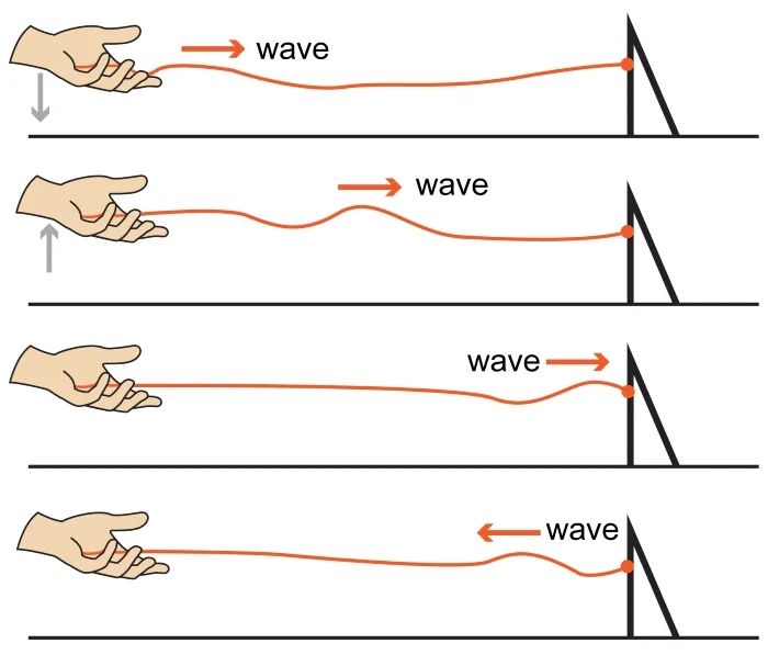
Understanding Wave Reflection in RF Design

DEVM in FEM RF Amplifier Output Power
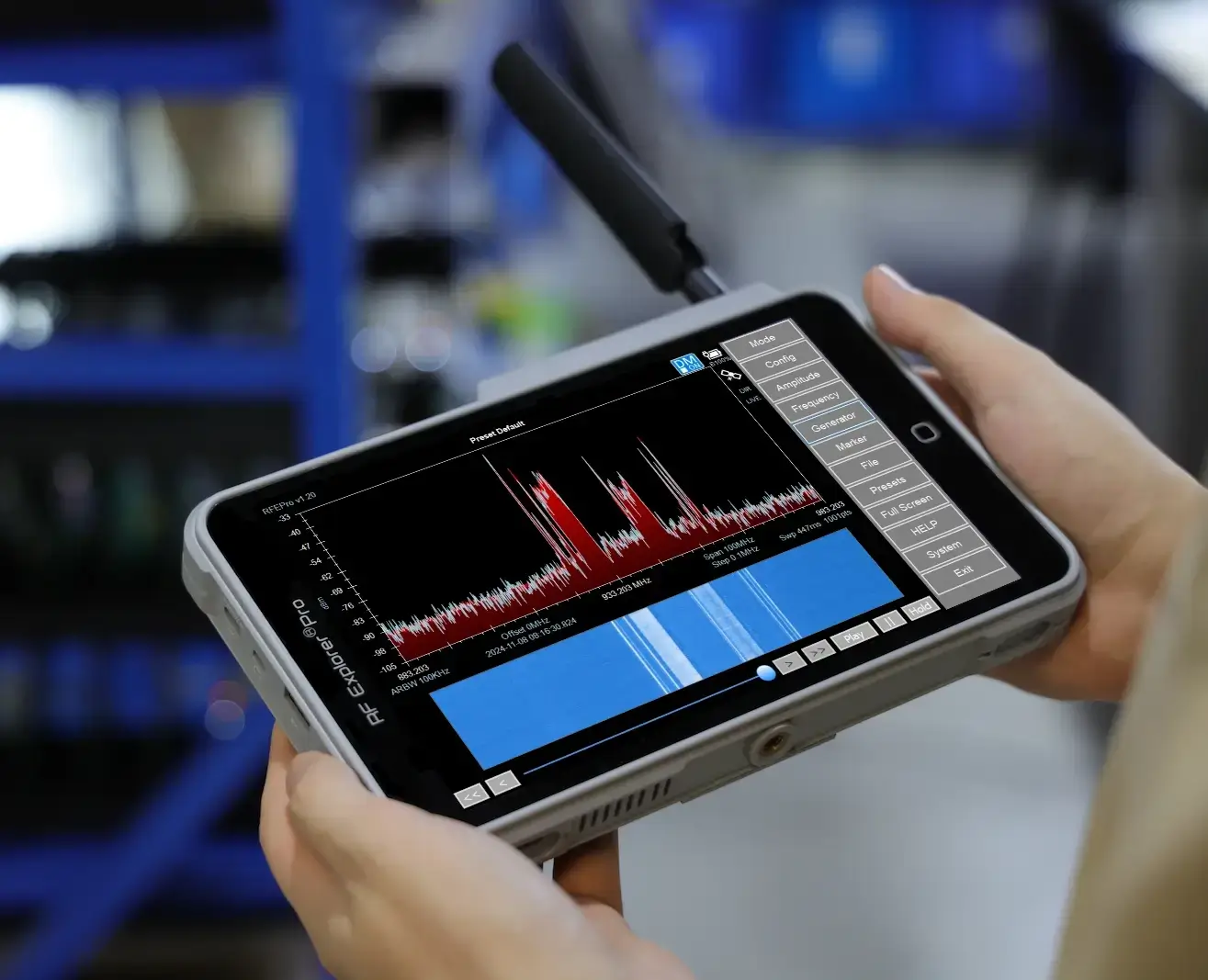
Spectrum Analyzers and Network Analyzers for RF PCB Design, Signal Integrity, and High-Frequency Manufacturing Validation
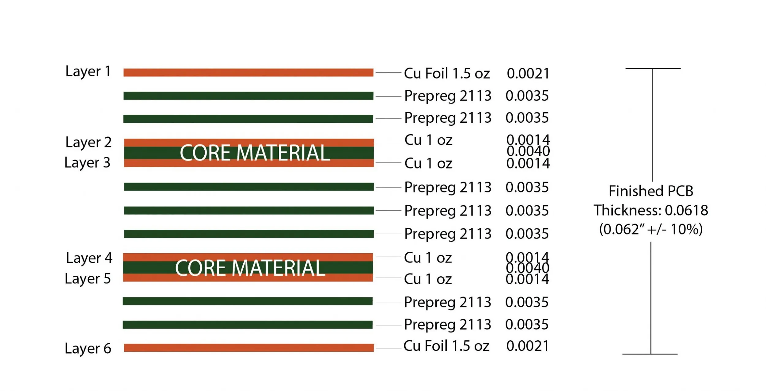
Multilayer PCB Design for RF Applications: Optimizing Performance at High Frequencies
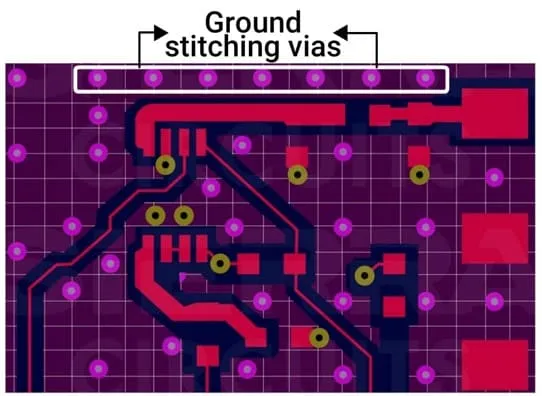
PCB Routing for RF Applications: Minimizing Signal Loss and Noise

High Speed PCB Routing: Achieving Impedance Control for Signal Integrity
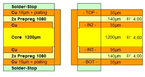
Signal Integrity in High Speed Designs: Leveraging 3 oz Copper PCBs
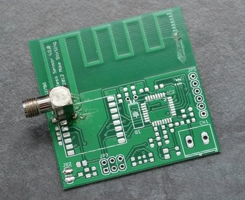
Antenna Design on High Frequency PCBs: Optimizing Performance
High Frequency PCB Design for Beginners: A Step by Step Guide
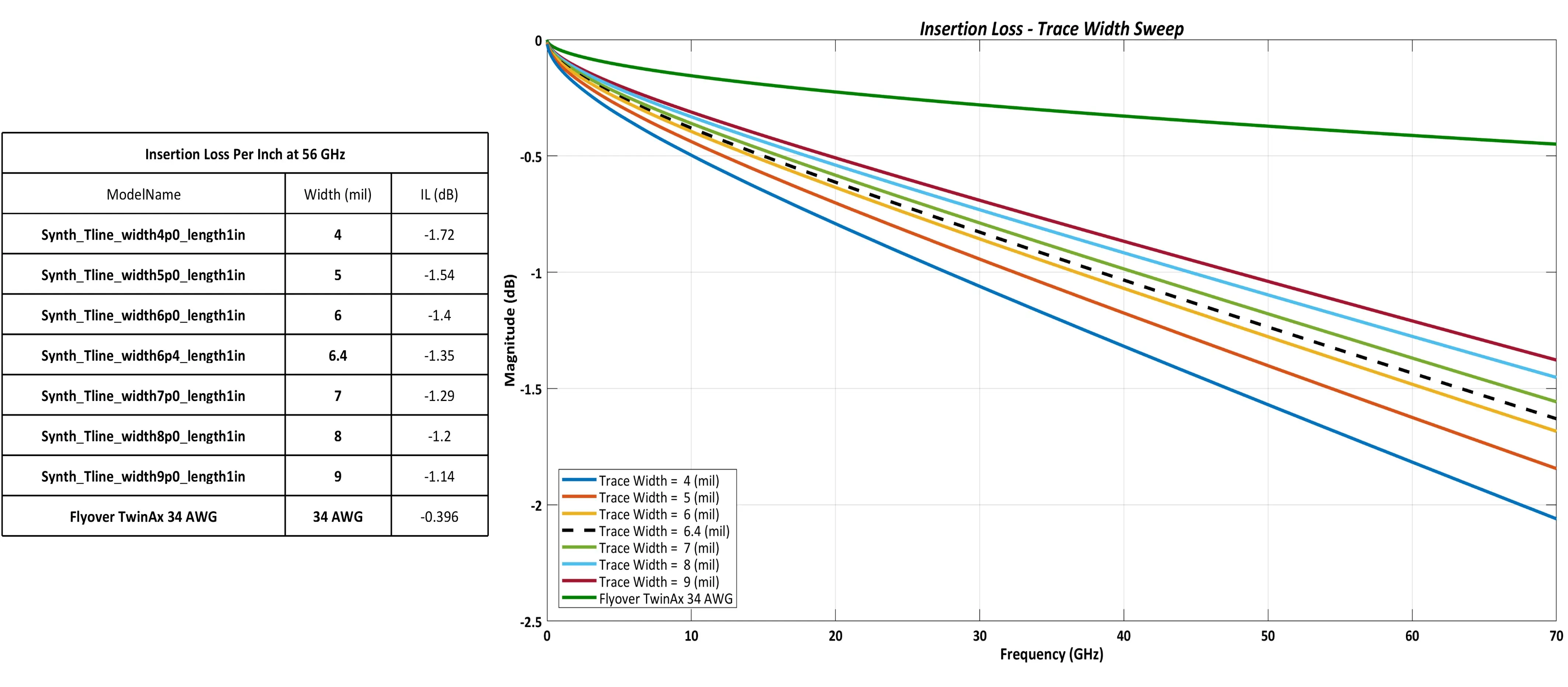
Signal Integrity Considerations for PTFE PCBs: Minimizing Loss and Maximizing Performance
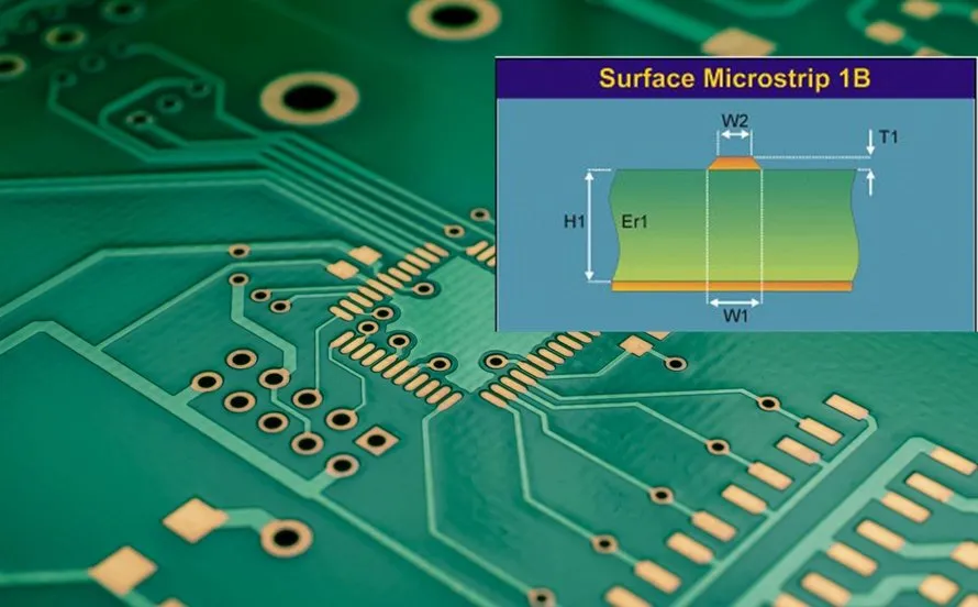
The Ultimate Guide to Designing PTFE PCBs for RF and Microwave Applications
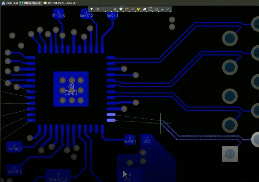
Optimizing PCB Stack Up for RF Applications: A Practical Guide

Optimizing PCB Signal Integrity with Ferrite Bead Filters: A Comprehensive Guide
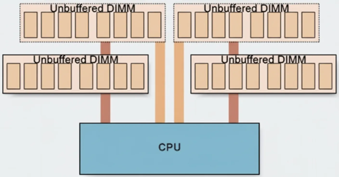
DDR3 and DDR4 Memory: Technical Notes
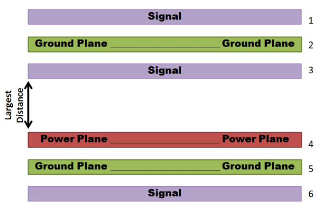
Mastering PCB Ground Plane Design for High-Speed Signal Integrity
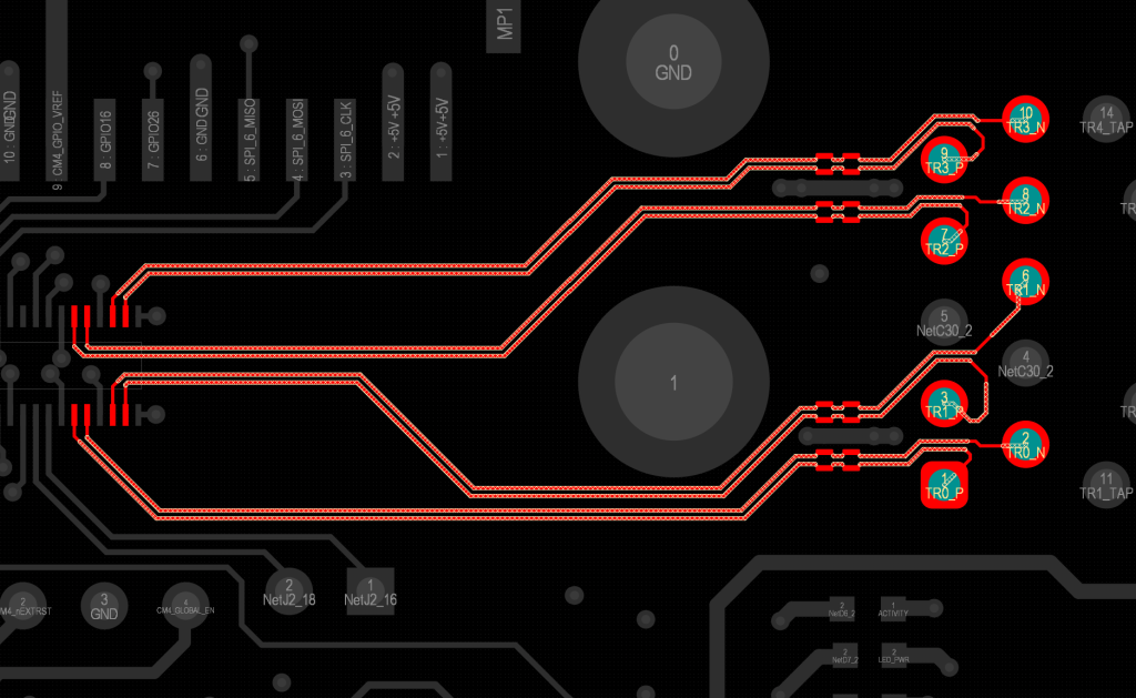
Via Placement for Differential Pairs: Maintaining Impedance and Signal Integrity

High Tg PCB Manufacturing for High Speed Digital Circuits
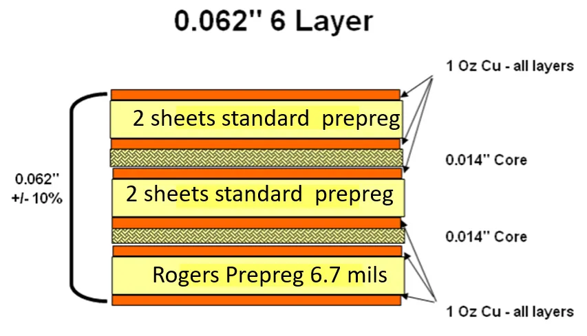
Rogers PCB Impedance Calculator: A Practical Guide


