IPC Standards
IPC Standards represent a cornerstone of the electronics industry, providing globally recognized guidelines for the design, manufacture, assembly, and inspection of printed circuit boards (PCBs) and related assemblies. Developed by the Association Connecting Electronics Industries (IPC), these standards ensure consistency, reliability, and quality across diverse applications, from consumer electronics to aerospace and medical devices. For engineers, designers, and manufacturers searching for information on IPC Standards, this tag serves as a comprehensive resource to understand their implementation and impact on product development cycles. At the heart of IPC Standards are practical frameworks that address real-world challenges in PCB fabrication and assembly. For instance, standards like IPC-A-610 outline acceptability criteria for electronic assemblies, helping teams identify defects and maintain high-quality outputs. Similarly, IPC-7351 provides land pattern guidelines for surface-mount components, enabling precise design practices that reduce errors and improve solder joint reliability. By adhering to these standards, professionals can mitigate risks such as thermal failures or signal integrity issues, ultimately leading to more robust and compliant products. This is particularly valuable for those involved in prototyping or scaling production, where compliance can streamline certification processes and enhance market competitiveness. Professionals often turn to IPC Standards for best practices in areas like material selection, soldering techniques, and rework procedures. Articles under this tag delve into actionable insights, such as how to apply IPC-6012 for rigid PCB qualification or integrate IPC-7711/7721 for repair and modification. Whether you are troubleshooting assembly issues or seeking updates on evolving standards like those for high-density interconnects, the content here offers in-depth analysis and case studies. Browsing these related articles can provide the knowledge needed to implement effective strategies in your projects, fostering innovation while upholding industry benchmarks.
Technical Articles
How to Fix SMD Edge Clearance, V-CUT Legend, and Gold Finger Issues in Class 3 PCB CAM Review
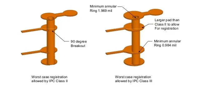
IPC Class 2 vs Class 3 HDI PCB Requirements: What Is Different?
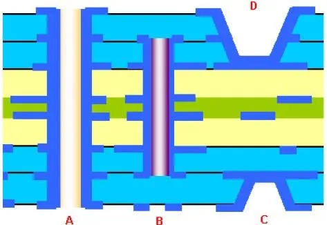
High Reliability Blind Via Design: Meeting Stringent Industry Standards
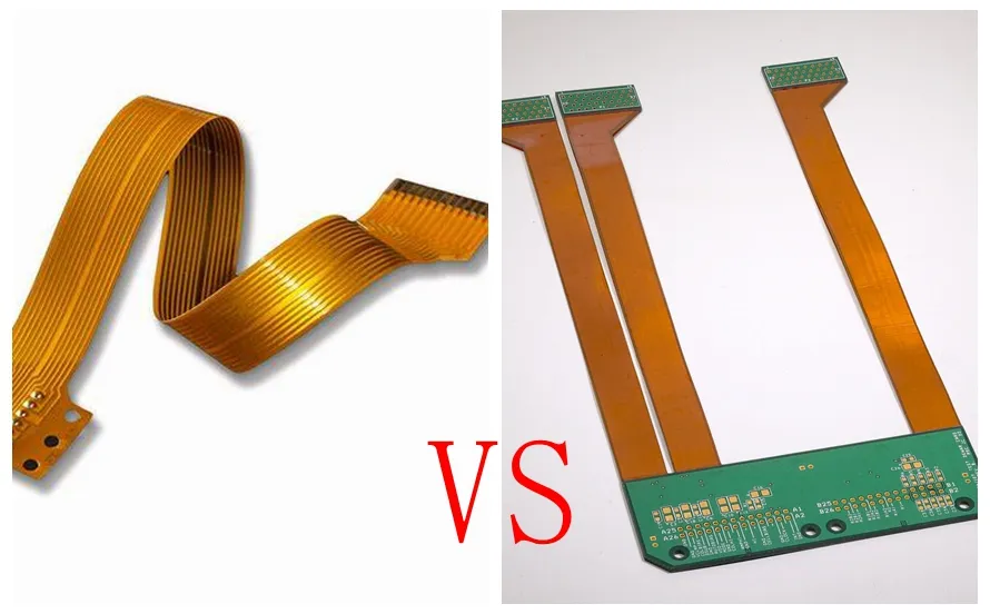
Overcoming Common Flex and Flex Rigid Design Challenges in PCB Design
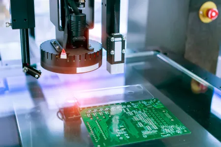
AOI Programming for Dummies: A Step by Step Guide to PCB Inspection
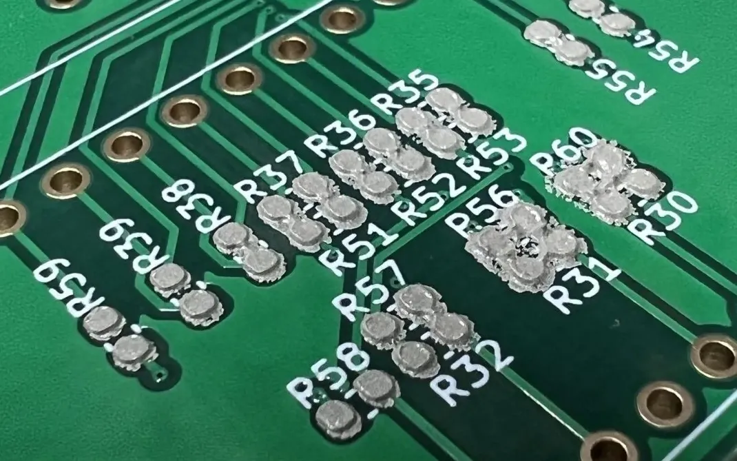
The Relationship Between PCB Pad Design and Solder Paste
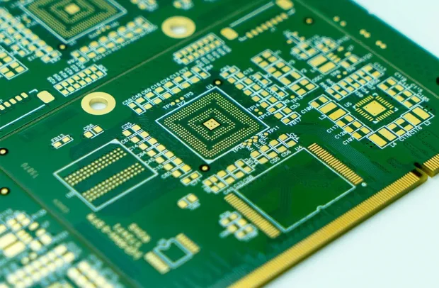
The Ultimate Guide to Selecting the Right Dry Film Solder Mask Thickness for Optimal PCB Performance

PCB Trace Width and Footprint Compatibility

Matte Finish vs. Gloss Finish: What you must know as a PCB designer
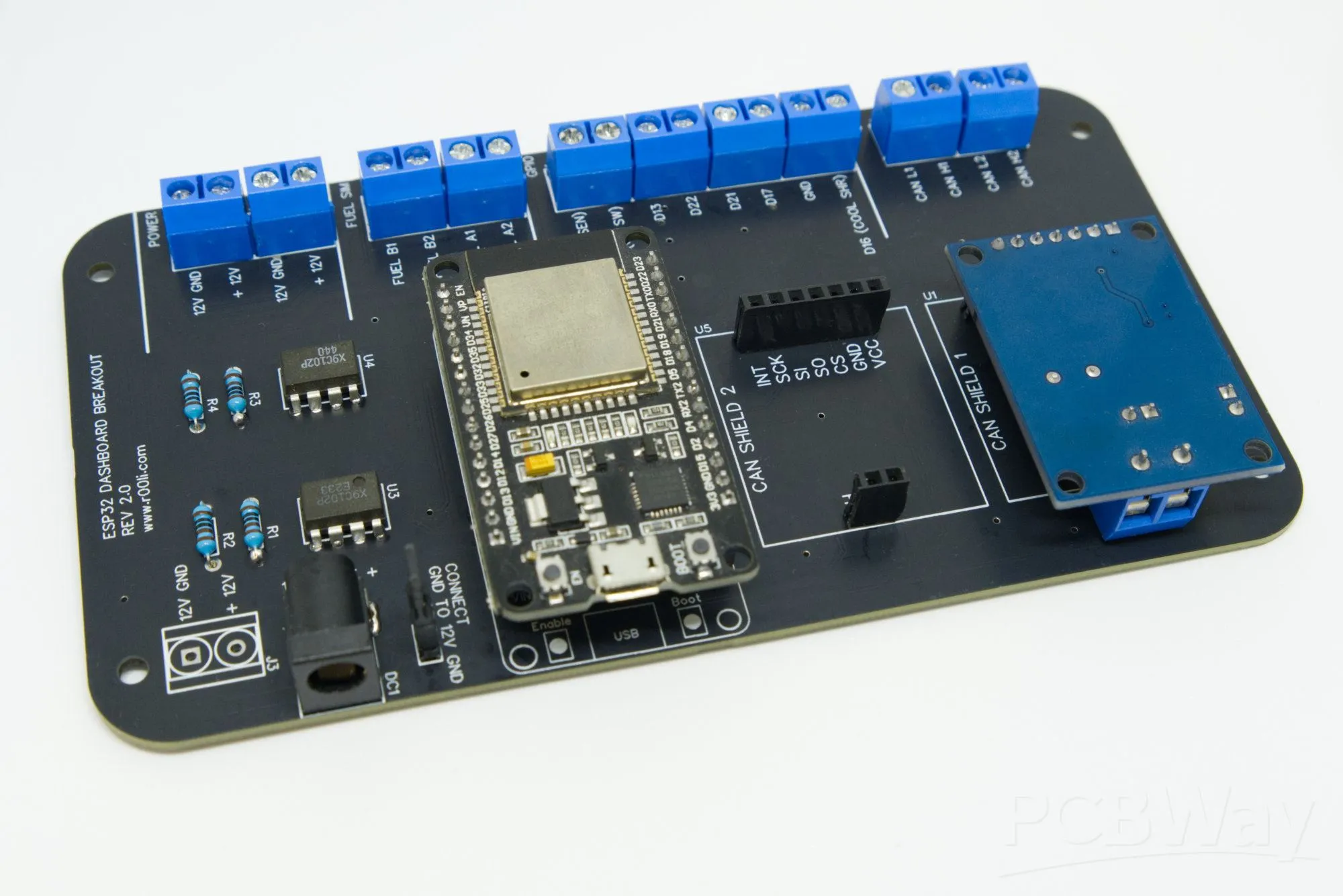
Automated PCB Design Review for DFM and DFA.
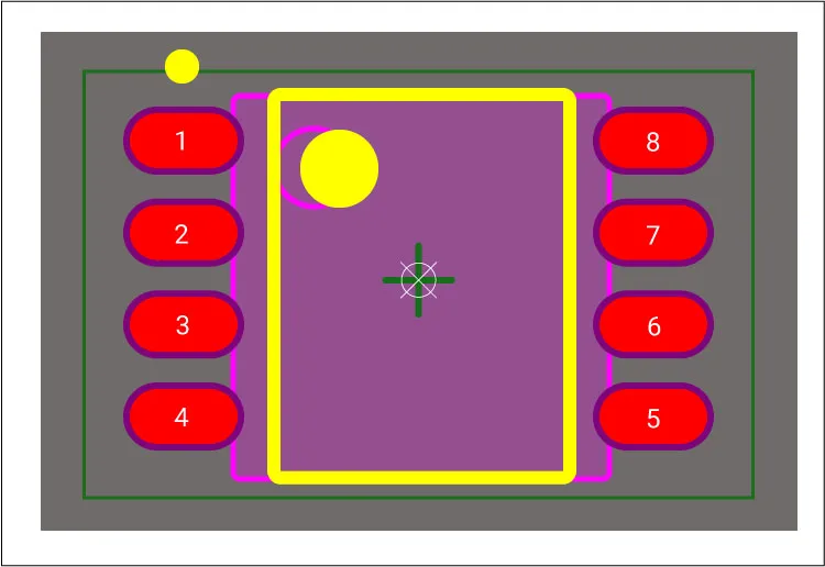
Component Footprints for SMT Assembly: Optimizing for Pick and Place Machines
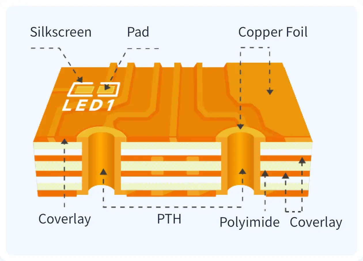
Flexible PCB Design for Extreme Temperatures: Material Selection and Reliability
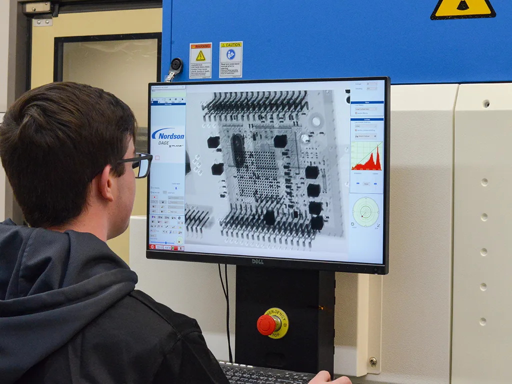
X Ray Vision for PCBs: Mastering Defect Detection in Electronics Manufacturing
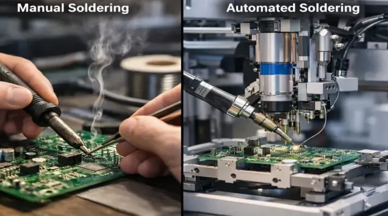
Manual Soldering Stations vs. Automated Systems: Which is Best for Your PCB Assembly Needs?

Troubleshooting Via Filling Defects: Identifying and Resolving Common Issues
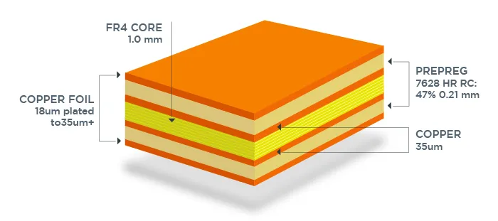
Copper Thickness in Mils: A Comparison of Different PCB Standards (IPC vs. Others)

IPC Standards Demystified: Inner Layer Copper Thickness Requirements for Reliable PCBs
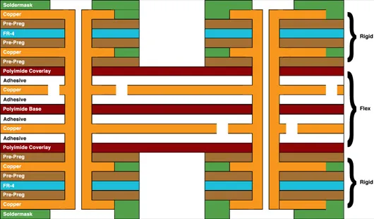
Mastering Rigid Flex PCB Bend Radius: A Practical Guide for Reliable Designs