 00:46
00:46
PCB Copper Weight
Understanding PCB copper weight is essential for engineers, designers, and manufacturers involved in printed circuit board development. PCB copper weight refers to the thickness of the copper foil used in the board's layers, typically measured in ounces per square foot (oz/ft²). This metric directly influences the board's electrical performance, thermal management, and overall durability. For instance, standard weights like 1 oz/ft² suit many general-purpose applications, while heavier options such as 2 oz/ft² or more are ideal for high-current circuits where enhanced conductivity and heat dissipation are critical. When selecting the appropriate PCB copper weight, consider factors such as current carrying capacity, voltage drop, and signal integrity. Thicker copper reduces resistance and minimizes voltage losses in power distribution networks, making it a key choice for automotive, aerospace, and industrial electronics. Practical applications include calculating trace widths to prevent overheating—using tools like IPC-2221 standards to determine minimum requirements based on amperage and temperature rise. Best practices recommend starting with simulations in design software to model thermal behavior, ensuring the chosen weight aligns with the project's environmental conditions and reliability goals. This tag on PCB Copper Weight gathers in-depth articles that explore these concepts, from beginner guides on measurement techniques to advanced discussions on multilayer board optimizations. Readers can find valuable insights into cost implications, as heavier copper increases material expenses but enhances longevity, and tips for prototyping to validate designs. By delving into these resources, you can make informed decisions that improve PCB efficiency and reduce failure risks in real-world implementations.
Video Guide
-
00:46
Technical Articles
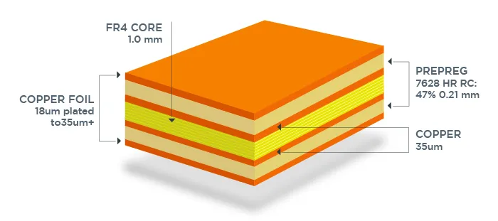
Copper Thickness in Mils: A Comparison of Different PCB Standards (IPC vs. Others)
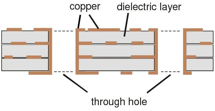
IPC Standards Demystified: Inner Layer Copper Thickness Requirements for Reliable PCBs
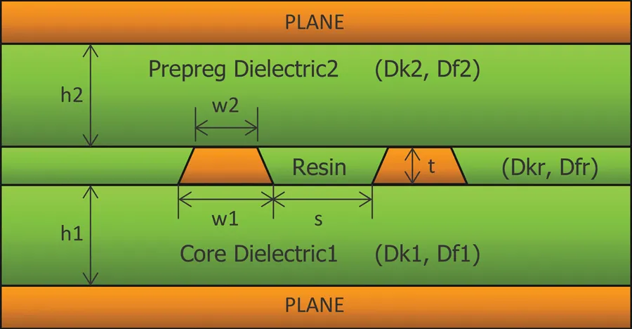
Copper Thickness in Mils and PCB Manufacturing Tolerances: What You Need to Know

Heavy Copper vs. Standard PCB: Choosing the Right Board
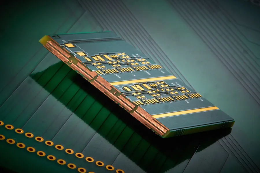
Beyond Standard: Exploring High Outer Layer Copper Thickness PCBs for High Power Applications

Power Integrity and PCB Trace Design: Minimizing Voltage Drop and Ensuring Stable Power Delivery
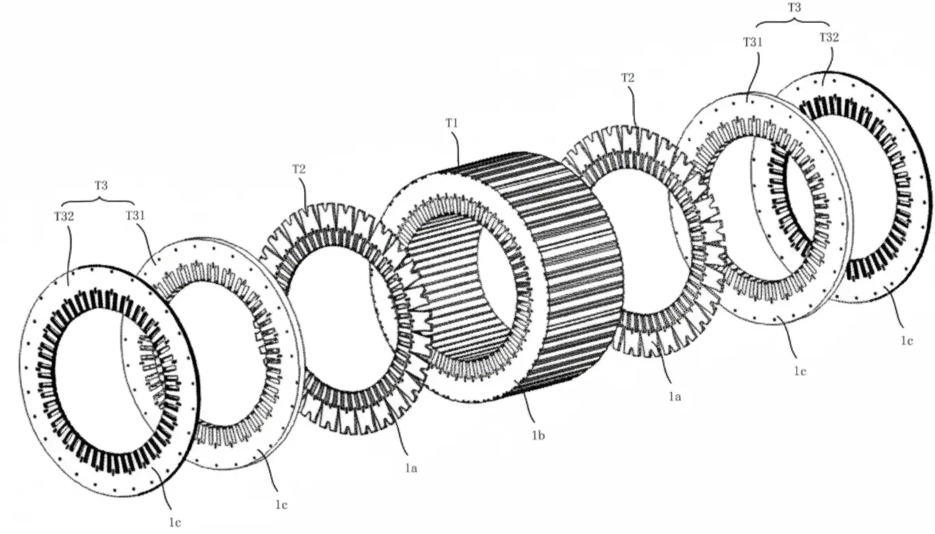
Oil-cooled Motor Cooling Designs
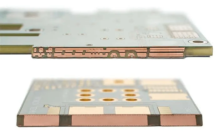
IPC Standards for PCB Copper Weight: Ensuring Quality and Reliability
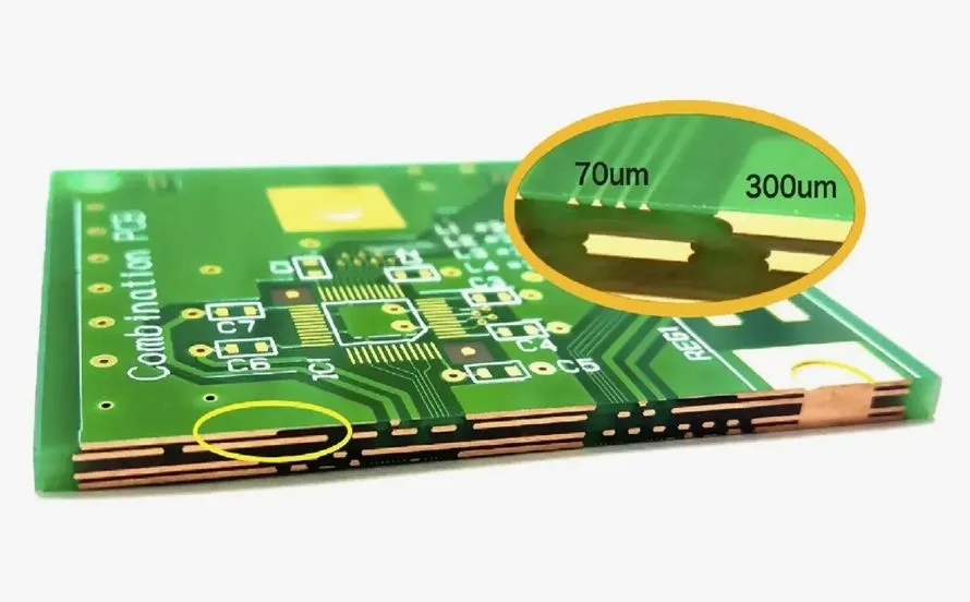
What You Need to Know About Copper Weight in PCB Design

6-Layer PCB Stackup for Power Electronics: High-Current & High-Voltage Design Guide
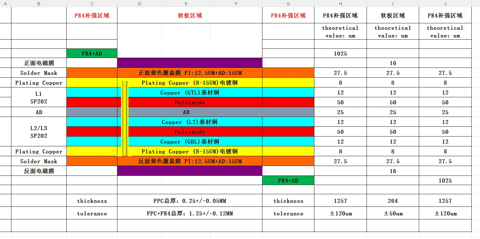
PCB Stackup, Impedance and Thickness Issues in CAM Review
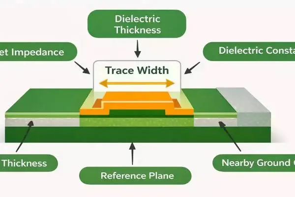
FR4 PCB Minimum Trace Width: What Designers Should Know

FR4 PCB Thermal Vias: Placement and Design Guidelines
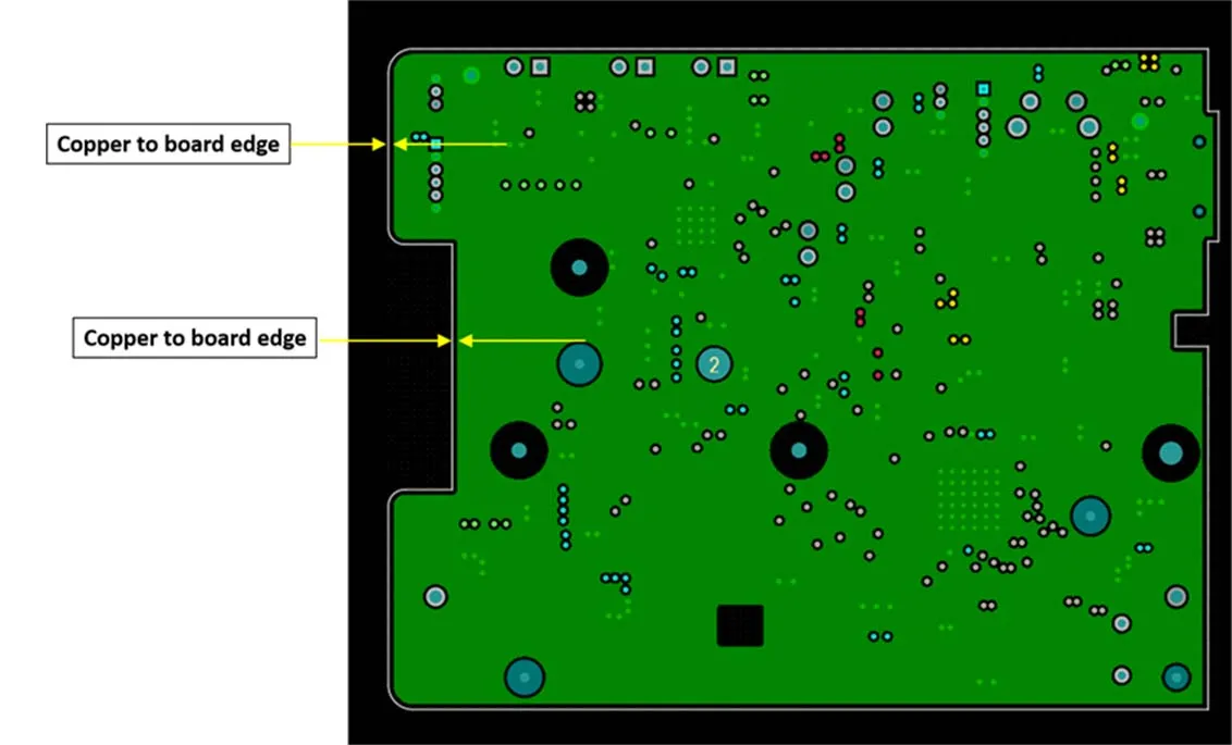
FR4 PCB Edge Clearance: How Much Copper Should Be Kept from the Board Edge?
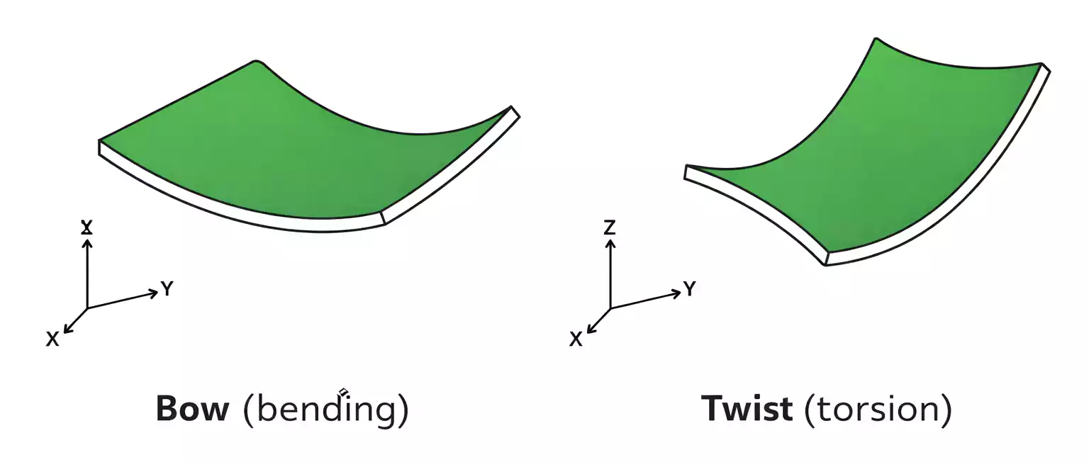
FR4 PCB Warpage and Twist: Manufacturing Causes and Solutions

FPC Copper Thinning: FPC Thickness Selection, Techniques and Design Guidelines
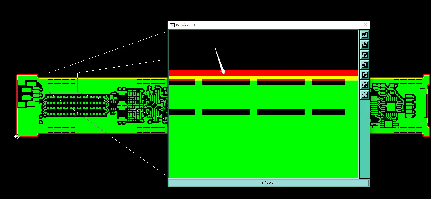
Preventing Exposed Copper from Copper to Outline Clearance Issues
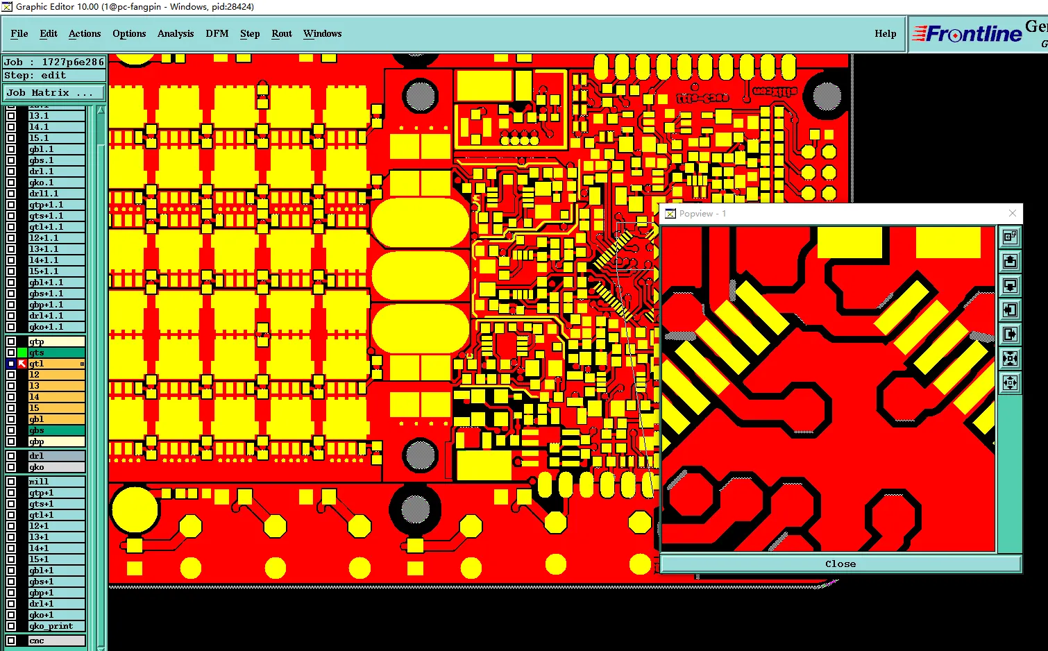
How DFM Prevented Heavy Copper Etch Failures in Multilayer PCB
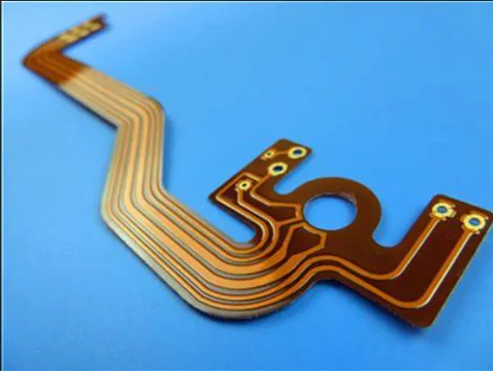
How Small Can FPC Line Width and Spacing Be in Production?