When a flexible printed circuit must carry a BGA, a high-pin-count ZIF connector, or a battery contact, the copper and polyimide alone cannot provide the local rigidity needed for reliable soldering or repeated insertion. Designers therefore add an FPC stiffener, also called reinforcement or backing material, exactly where mechanical support is required while leaving the rest of the circuit free to bend. Choosing the wrong stiffener material is one of the most common sources of assembly scrap, solder-joint fatigue, and field failures. Use FR4 when cost and high rigidity under SMT components matter most; switch to polyimide when overall thickness and residual flexibility are critical; reserve stainless steel for the highest insertion forces or the thinnest possible profiles.
Highlights:
● FR4 remains the default for most consumer SMT pads because it is inexpensive and easy to route.
● Polyimide stiffeners match the CTE of the base FPC and keep the stack thin enough for wearables and medical devices.
● Stainless steel delivers maximum hardness in 0.05–0.2 mm thickness but demands electrical isolation and careful adhesive selection.
● Abrupt thickness steps next to dynamic bend zones are the leading cause of copper cracking.
● Total cost of ownership often favors a slightly more expensive material that raises first-pass yield.
In the sections that follow you will find a clear FPC material comparison, bonding and reliability guidance, thickness and placement rules, a practical selection framework, and lessons from real production.
Why Use Stiffener in FPC Design?
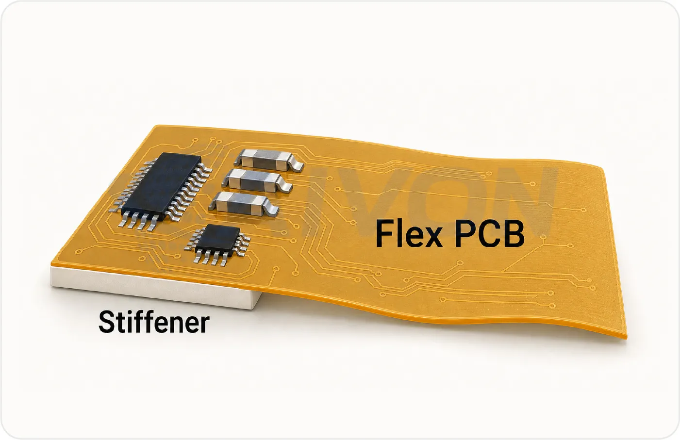
An FPC stiffener is a discrete patch of rigid or semi-rigid material laminated to one or both sides of the flexible circuit. Its core job is to supply localized mechanical support exactly where the polyimide core alone is too soft.
Primary functions are as follows:
● Create a flat, stable platform so components can be placed accurately and survive reflow without warpage.
● Absorb the insertion and extraction forces of ZIF, board-to-board, or battery connectors so the copper traces and solder joints do not tear.
● Protect fine-pitch traces from handling damage during assembly and rework.
Secondary but equally important roles include controlling the local bend radius at the edge of the stiffener and providing a rigid reference edge that vacuum nozzles or fixtures can grip reliably.
These reinforced zones typically sit under BGA or QFN footprints, on the tongue of a connector, at battery-contact pads, or along any edge that must be handled by automation. In smartphones, wearables, automotive camera modules, and medical devices the stiffener is often only a few millimeters away from dynamic flex regions that may see tens of thousands of bend cycles. Because the stiffener is so close to both rigid components and moving flex areas, its material properties—flexural modulus, thickness tolerance, CTE, thermal conductivity, and electrical behavior—directly influence every process step that follows and the long-term reliability of the finished product.
That is why the choice among FR4, polyimide, and stainless steel is never just a cost decision. A CTE mismatch between the stiffener and the polyimide base leaves residual stress after reflow; the result is solder-joint cracks or coverlay delamination at the stiffener edge. An electrically conductive stainless-steel stiffener that is not properly isolated creates short circuits or unwanted EMI paths. An FR4 stiffener that is thicker than necessary pushes the total stack height beyond the mechanical envelope of a slim housing and can cause assembly or drop-test failures. Even a well-intentioned polyimide stiffener can be too compliant under a high-pin-count connector, leading to incomplete mating or accelerated wear.
These failure modes appear regularly on failure-analysis reports and in field returns. The material therefore has to be matched not only to the mechanical load but also to the thermal profile, electrical isolation requirements, and thickness budget of the specific design.
Core FPC Stiffener Material: FR4, Polyimide, and Stainless Steel
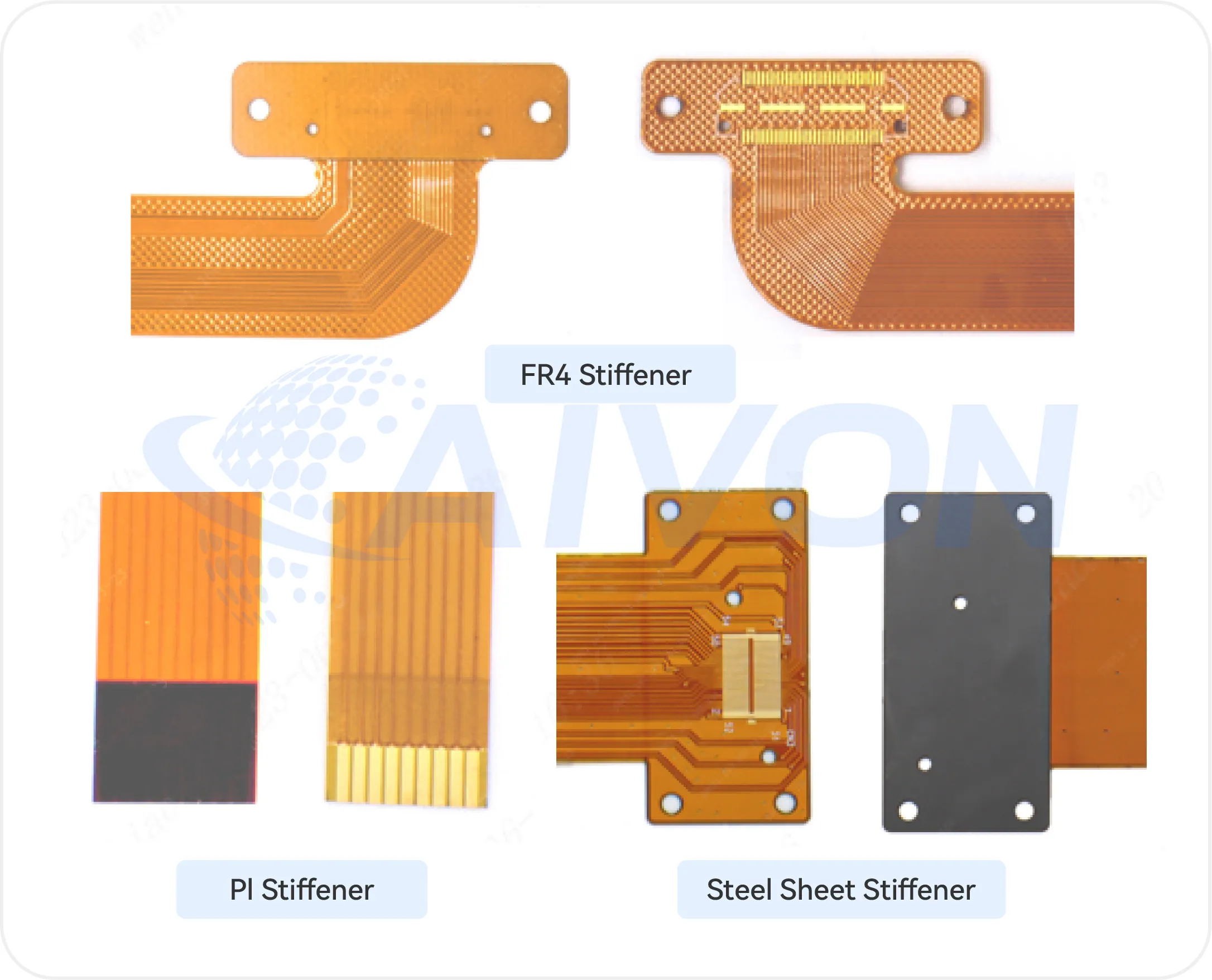
Typically, stiffeners in flex PCB manufacturing are made up of Polyimide, FR-4, and Stainless Steel. FR4 remains the default for many high-volume consumer designs because it is rigid, inexpensive, and easy to machine. Polyimide stiffeners stay in the conversation when the designer cannot afford the thickness of FR4 or needs the same thermal expansion behavior as the base film. Stainless steel appears when insertion force or wear resistance exceeds what either polymer can deliver.
FR4 Stiffeners
FR4 is a widely used stiffener material for the flex PCB design because it provides good rigidity at a relatively low cost. Their flexural modulus is high enough that a 0.3 mm piece under a QFN keeps the pads flat through lead-free reflow. CNC routing or laser cutting produces clean edges, and the material is available in every thickness a fabricator already stocks for rigid panels.
The limitations appear as soon as the design tightens. FR4's CTE is roughly 14–17 ppm/°C in the plane, while polyimide film sits closer to 12–20 ppm/°C depending on the grade and orientation. That mismatch creates residual stress that can open micro-cracks in the adhesive or the copper after repeated thermal cycles. FR4 is also relatively thick; once the total stack exceeds the mechanical envelope, designers start looking elsewhere. Finally, FR4 itself does not flex, so any area that must still bend after assembly is off-limits.
In practice FR4 is the first choice for static SMT zones, test-point arrays, and low-cycle insertion connectors in consumer electronics where cost and process familiarity dominate.
Polyimide Stiffeners
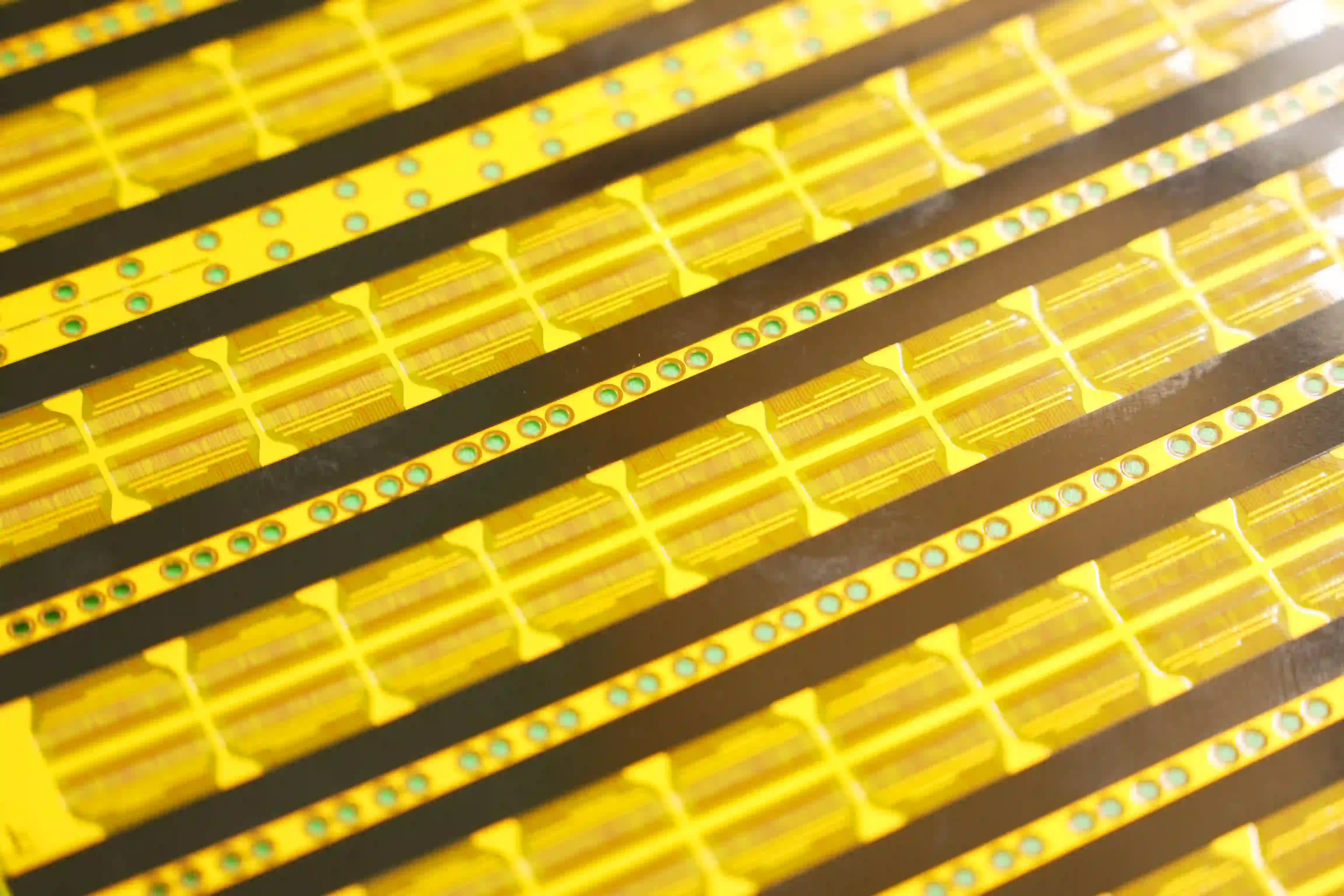
Polyimide (PI) is another common material for FPC stiffeners, particularly when a thinner and lighter reinforcement is required. Polyimide stiffeners are cut from the same family of films used for the FPC coverlay and base, usually 0.025 mm to 0.25 mm thick. Because the CTE is nearly identical to the circuit film, residual stress after lamination and reflow stays low. The material survives lead-free reflow temperatures without degradation and retains useful mechanical properties at continuous operating temperatures well above 150 °C.
The absolute stiffness is lower than FR4 of the same thickness, so a PI stiffener is rarely the right answer for a heavy BGA that must remain perfectly flat. Its value appears when the designer needs some residual flexibility, ultra-thin total stack height, or chemical resistance that matches the rest of the flex. Medical wearables, aerospace flex circuits, and multi-layer dynamic-flex zones routinely use PI for exactly these reasons.
Material cost is higher than FR4, and the thin gauge makes handling more delicate. Adhesive selection becomes critical; a mismatched acrylic can introduce creep under continuous load that FR4 would never notice.
Stainless Steel Stiffeners
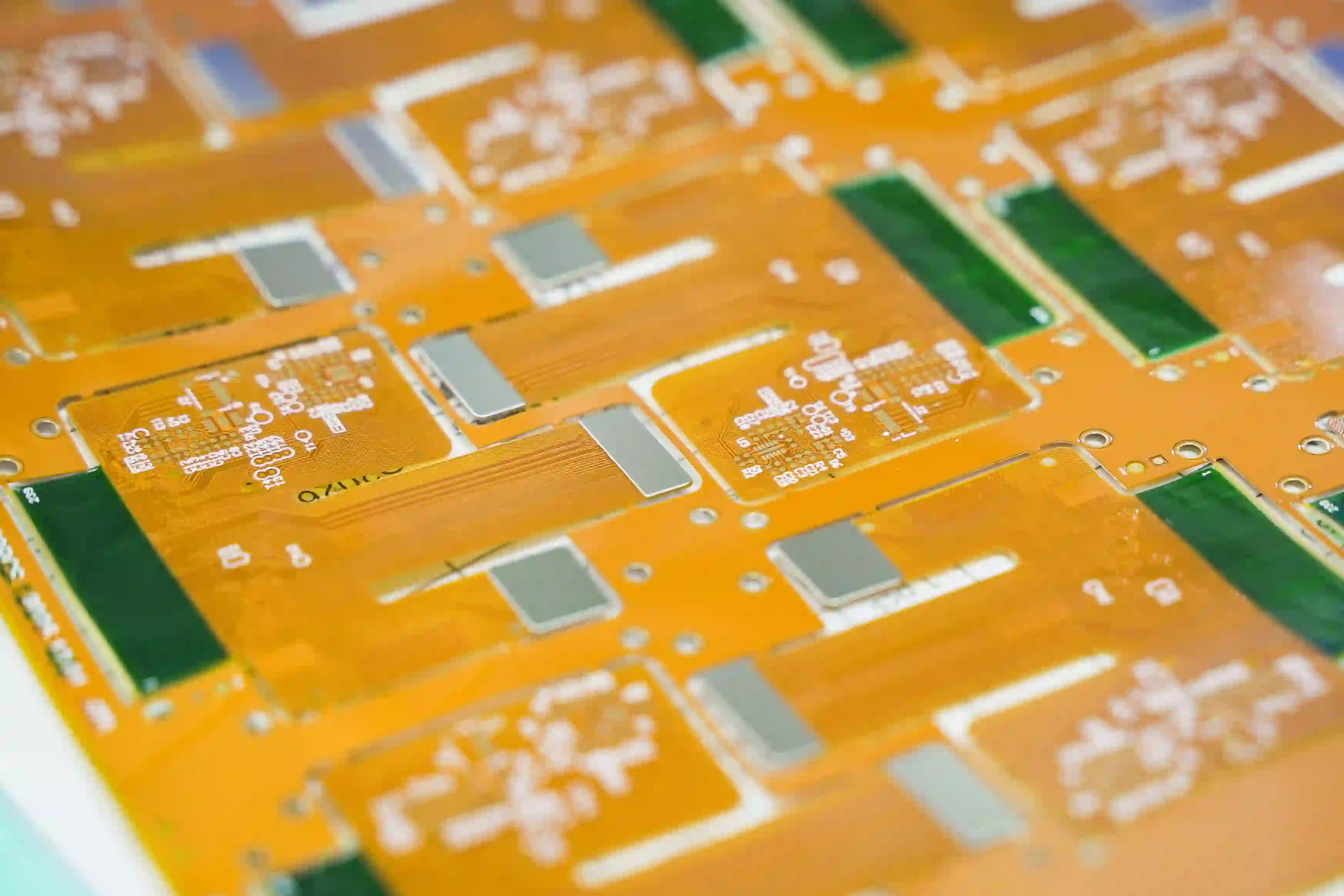
Stainless steel provides substantially higher mechanical rigidity than polymer-based stiffener materials. A stainless steel stiffener for flex PCB applications can therefore be useful when a thin reinforced area must withstand relatively high mechanical loads..
Two engineering constraints dominate FPC stiffener design. First, steel is electrically conductive. Unless the stiffener is deliberately used as a ground plane or shield, an isolation layer (coverlay, adhesive film, or solder mask) must be present. Second, galvanic corrosion risk rises when copper traces or solder joints sit in electrical contact with the steel in a humid environment; proper isolation and edge sealing eliminate the path. Bonding also requires more process control—surface preparation, adhesive thickness uniformity, and sometimes a pre-bake to drive off moisture—than the polymer options.
When those constraints are managed, stainless steel is the clear choice for board-to-board connectors that see high insertion force, industrial sensors that must survive vibration, and any location where the mechanical envelope simply will not accept a thicker polymer stiffener.
FPC Stiffener Property Comparison
The following table summarizes the practical differences that drive selection decisions.
|
Material |
Typical Thickness |
Flexural Rigidity |
CTE Match to FPC |
Thermal Resistance |
Electrical Conductivity |
Relative Cost |
Best For |
Key Limitations |
|---|---|---|---|---|---|---|---|---|
|
FR4 |
0.2–1.65mm |
High |
Moderate |
Good |
Insulating |
Low |
SMT pads, cost-sensitive designs |
Thickness, limited flexibility |
|
Polyimide(PI) |
0.05–0.15 mm |
Medium |
Excellent |
Excellent |
Insulating |
Medium–High |
Thin wearables, medical, residual flex |
Lower absolute stiffness |
|
Stainless Steel |
0.15–0.2 mm |
Very High |
Poor |
Excellent |
Conductive |
High |
High-force connectors, minimal thickness |
Isolation required, higher cost |
How to Attach an FPC Stiffener: Bonding Process and Process Control
Attaching a stiffener is more than simply applying glue. The process must deliver a permanent, void-free bond that survives reflow, thermal cycling, humidity, and mechanical load while preserving the dimensional accuracy of the flexible circuit. The sequence typically includes FPC surface finish preparation, adhesive application or film placement, precise alignment, lamination under controlled heat and pressure, and post-bond inspection.
Three adhesive systems dominate production and are selected according to the stiffener material and end-use requirements.
|
Adhesive Type |
Bonding Conditions |
Typical Use Cases |
Key Advantages |
Limitations |
|---|---|---|---|---|
|
Pressure-sensitive (PSA) |
Room-temperature bonding |
Thin polyimide or light-duty stainless-steel stiffeners |
Fast process, simple application |
Creep under sustained load; rarely used for high-insertion-force connectors or automotive |
|
Thermosetting epoxy films |
Heat and pressure cure |
FR4 stiffeners under BGAs or QFNs |
Highest peel strength and temperature resistance |
Cure profile must be matched to FPC stack to avoid warpage |
|
Acrylic/hybrid films |
Moderate heat and pressure |
Broad consumer and industrial applications |
Wider process window, good long-term stability |
Intermediate performance between PSA and epoxy |
The most common field failures originate in the bond line itself—edge delamination after thermal shock, adhesive creep under continuous connector load, and moisture-driven corrosion at the steel–copper interface. These risks are screened by peel-strength testing to IPC-TM-650, thermal-shock cycling (typically –40 °C to +125 °C), and humidity-bias testing. When the stiffener sits under fine-pitch BGAs, acoustic-microscopy inspection on first-article lots is routinely added at AIVON; the non-destructive image of the bond interface catches voids that electrical test alone cannot detect.
A correctly executed attachment process therefore combines the right adhesive chemistry, material-specific lamination conditions, surface preparation where needed, and targeted inspection. Only then do the mechanical advantages of the chosen stiffener material translate into reliable, high-yield production.
FPC Stiffener Thickness and Placement Design Rules
FPC stiffener thickness should be selected according to the mechanical requirements of the reinforced area, the FPC stack-up, and the available mechanical space. There is no single stiffener thickness that is appropriate for every flexible PCB application.
The design should consider at least four factors:
- The rigidity required by the component or connector.
- The total thickness allowed by the mechanical assembly.
- The transition between the stiffened and flexible sections.
- The manufacturing tolerance of the stiffener and adhesive layers.
FPC Stiffener Thickness
A thicker stiffener generally provides greater local rigidity, but increasing thickness can also increase the overall stack height and create a more abrupt transition into the flexible area.
For example, a connector may require a relatively rigid backing to support insertion force, while a thin wearable circuit may require only modest reinforcement. In the latter case, an excessively thick stiffener can make routing or bending around the reinforced area more difficult.
For a flexible PCB with a stiffener, the final thickness should therefore be checked against the complete assembly rather than considered separately from the FPC.
FPC Stiffener Placement
Placement determines where the FPC becomes rigid and where it remains flexible. The stiffener should normally be limited to the area that requires mechanical reinforcement.
Common stiffener locations include:
- Connector contact areas.
- SMT component areas.
- Battery contact areas.
- Mounting or fastening locations.
- Areas subject to repeated handling.
The stiffener edge should be positioned carefully relative to bend zones, plated features, holes, traces, and exposed pads. An abrupt transition too close to a dynamic bend can concentrate mechanical stress and increase the risk of copper fatigue.
For this reason, flex PCB stiffener placement should be reviewed during the initial FPC design stage rather than added after the layout is completed.
How to Choose the Right FPC Stiffener
When choosing a stiffener for a flex PCB, the decision usually comes down to a few practical factors in this rough order: the type of mechanical load (static versus repeated insertion or vibration), how much thickness you can spare, the thermal environment, whether electrical isolation is needed, and finally the unit cost at the volumes you're targeting.
In consumer smartphones or tablets, where the SMT area won't see any dynamic flex after assembly, FR4 is still the lowest total-cost choice.
Ultra-thin wearables or medical patches that have to keep bending almost always go with polyimide (PI), often paired with a low-outgassing adhesive.
High-pin-count board-to-board connectors or industrial sensor contacts typically need stainless steel, which provided isolation and corrosion protection are designed in from the start.
When the requirements pull in opposite directions, such as thin profile + high force + some residual flexibility, hybrid stacks make the most sense: a thin steel piece under the connector and a PI stiffener under the nearby components, or FR4 in the SMT zone and PI in the transition zone.
It's worth looking at total cost of ownership rather than just the piece price. A slightly more expensive PI stiffener that improves SMT yield by a couple of percent or removes a field-return mode will often beat the cheapest FR4 option.
AIVON Case Study: When the Stiffener Crept Too Close to the Gold Fingers
In DFM review we caught a detail that looked minor on the Gerber but would have caused real trouble later.
The customer's stiffener outline stopped almost exactly at the edge of the gold-finger insertion zone. That left virtually no unsupported flexible length between the rigid reinforced area and the connector fingers. On the drawing it appeared neat; in actual use it meant every insertion and extraction would force a sharp bend right at the stiffener edge.
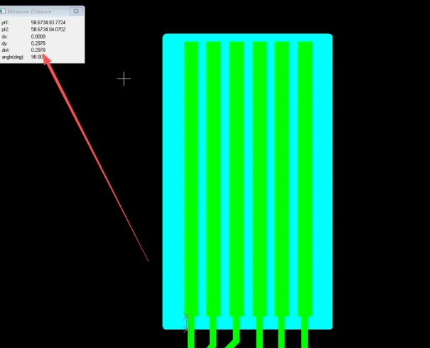
We flagged it immediately. Our recommendation was simple and practical: enlarge the stiffener so its edge sits 0.5 mm away from the gold-finger area. That short flexible transition zone gives the board a controlled place to bend instead of concentrating all the stress at one hard line.
If the board had gone into production with the original dimensions, repeated mating cycles would have loaded the gold fingers and the nearby copper traces with concentrated bending stress. Over time you would see cracking in the finger area, fatigue fractures in the copper, intermittent contact, and a noticeably shorter service life, especially on products that get plugged and unplugged often.
After we walked the customer through the mechanical risk, they accepted the change. The stiffener was enlarged to maintain the 0.5 mm clearance. The revised design spreads the bending load more evenly and significantly improves insertion durability.Engineering note
When a stiffener sits next to connector fingers, always leave a deliberate transition distance. 0.5 mm is a reliable starting value that balances support and flexibility for most designs. The exact number should still be checked against the specific connector and expected cycle life, but never let the stiffener edge land directly against the gold fingers.
Practical Guidelines for Specifying FPC Stiffeners
Choosing the right FPC stiffener starts with understanding what the application actually requires. FR4 remains the practical choice for cost-effective designs that need strong mechanical support. Polyimide is preferred when thin profiles, high-temperature resistance, or partial flexibility are critical. Stainless steel provides superior rigidity and durability for ultra-thin, high-force, or wear-sensitive applications, as long as proper electrical and corrosion isolation is considered.
In many real-world designs, a single stiffener material cannot satisfy every requirement. Hybrid stiffener structures can balance mechanical strength, flexibility, thickness, and reliability when different areas of the flexible circuit face different challenges.
The most reliable FPC designs treat stiffener selection as part of the entire flex circuit system—not as a component added at the final stage. Stiffener thickness, adhesive selection, placement near bend areas, and isolation requirements must be considered together during the design process. By making these decisions early and validating them with manufacturing expertise, engineers can achieve the required performance while avoiding unnecessary cost and over-engineering.
FAQ
Q1: When is stainless steel the better choice over FR4 for a flexible PCB connector area?
A1: Use stainless steel when insertion force, repeated mating cycles, or a very tight thickness envelope exceed what FR4 can deliver. Stainless steel can be as thin as 0.05–0.15 mm while still resisting permanent deformation. Electrical isolation layers and corrosion protection should be incorporated into the design; otherwise, FR4 remains the simpler and more cost-effective option.
Q2: How thin can an FPC stiffener be while still supporting SMT components through reflow?
A2: For FR4, 0.2–0.3 mm is a common practical minimum for supporting fine-pitch packages. PI stiffeners can be as thin as 0.05–0.1 mm for lightweight components when paired with a high-modulus adhesive. Stainless steel at 0.05–0.1 mm is commonly used for connectors and small packages. The final thickness depends on component weight, pad geometry, and the adhesive's ability to maintain coplanarity during reflow.
Q3: Does a stainless-steel stiffener always need electrical isolation, and how is it achieved?
A3: Electrical isolation is required unless the stainless steel is intentionally used as a ground or shielding plane. Isolation is typically achieved using continuous coverlay, an insulating adhesive film, or a patterned solder mask between the steel and copper features. Edge sealing also helps prevent moisture ingress that could lead to galvanic corrosion.
Q4: Can different stiffener materials be mixed on the same FPC?
A4: Yes. Hybrid stiffener constructions are common. For example, FR4 may be used beneath a large BGA, PI in a transition zone, and stainless steel under a high-force connector. Each material is bonded with a compatible adhesive, and transition areas are carefully designed to avoid abrupt stiffness changes near bending regions.
Q5: What reliability tests should be run after stiffener attachment before releasing a design to volume?
A5: A practical qualification set includes peel-strength testing (IPC-TM-650), thermal shock or thermal cycling that matches the product profile, humidity-bias exposure, and bend-to-failure cycling for dynamic flex circuits. For fine-pitch areas beneath the stiffener, acoustic microscopy or X-ray inspection of the bond line is recommended to detect voids that electrical testing alone cannot identify.
Q6: Can an FPC have more than one stiffener?
A6: Yes. An FPC can use multiple stiffeners when different areas of the circuit have different mechanical requirements. For example, separate reinforced regions may be used for multiple connectors, component areas, or mounting features. Each stiffener should be defined as part of the overall FPC construction so that the reinforced areas do not interfere with required flexible regions.
Q7: Does an FPC stiffener affect the flexible area of the circuit?
A7: An FPC stiffener does not inherently eliminate flexibility across the entire circuit. Its effect is localized to the reinforced region and its immediate transition area. The actual impact depends on the stiffener outline, construction, and how close the reinforcement is to areas intended to bend.
Q8: Can an FPC stiffener be removed or replaced after manufacturing?
A8: In most cases, an FPC stiffener is intended to be a permanent part of the finished flexible circuit. Removing it after manufacturing can damage the FPC, adhesive interface, coverlay, or copper features. If a design may require later modification, the stiffener construction should be considered before fabrication rather than treated as a removable component.
Q9: Does every flexible PCB need an FPC stiffener?
A9: No. A stiffener is only necessary when a particular area of the flexible circuit requires additional mechanical support. Some FPCs are designed to remain flexible throughout most or all of their construction, while others use localized reinforcement for specific functional or assembly requirements.
Q10: Should FPC stiffeners be shown in the manufacturing files?
A10: Yes. The stiffener material, thickness, outline, location, and relevant manufacturing requirements should be clearly defined in the fabrication documentation. Clear documentation helps the manufacturer distinguish the stiffener from other FPC layers and reduces the risk of incorrect material selection or placement.
Q11: Can an FPC stiffener be used in a dynamic flexing area?
A11: A stiffener is generally intended for areas that need reinforcement rather than areas designed for repeated dynamic flexing. If reinforcement is required near a moving section, the boundary between the reinforced and flexible regions should be evaluated carefully during design to ensure that the circuit can achieve its intended movement without creating excessive mechanical stress.