 00:56
High Current Traces
High current traces are essential components in printed circuit board (PCB) design, engineered to safely carry substantial electrical loads without excessive heat buildup or voltage drops. In applications ranging from power electronics to automotive systems, these traces prevent failures by distributing current efficiently across the board. Designers often encounter challenges like thermal management and signal integrity when working with high current paths, making it crucial to understand the fundamentals of trace sizing, material selection, and layout optimization. When searching for information on high current traces, users typically seek practical guidance to enhance their PCB projects. Key considerations include calculating trace width based on current ratings, copper thickness, and ambient temperature using standards like IPC-2152. For instance, wider traces or multiple parallel paths can reduce resistance and improve performance in high-power scenarios, such as battery management systems or motor controllers. Best practices also involve incorporating thermal vias, heat sinks, and proper grounding to mitigate hotspots and ensure long-term reliability. By applying these techniques, engineers can avoid common pitfalls like trace burnout or electromagnetic interference, leading to more robust and efficient designs. Articles tagged under High Current Traces offer in-depth explorations of these topics, including step-by-step tutorials on simulation tools and real-world case studies. Whether you are troubleshooting an existing board or starting a new prototype, reviewing these resources can provide the insights needed to implement effective solutions. For related discussions on PCB thermal management or power distribution networks, the connected articles delve into complementary strategies that build on high current design principles.
Video Guide
-
00:56
Technical Articles
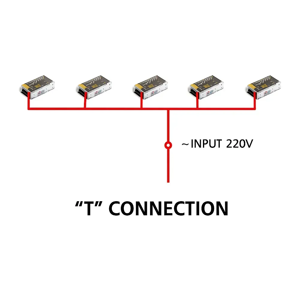
LED Display 220V Power Cable: Straight vs T Wiring
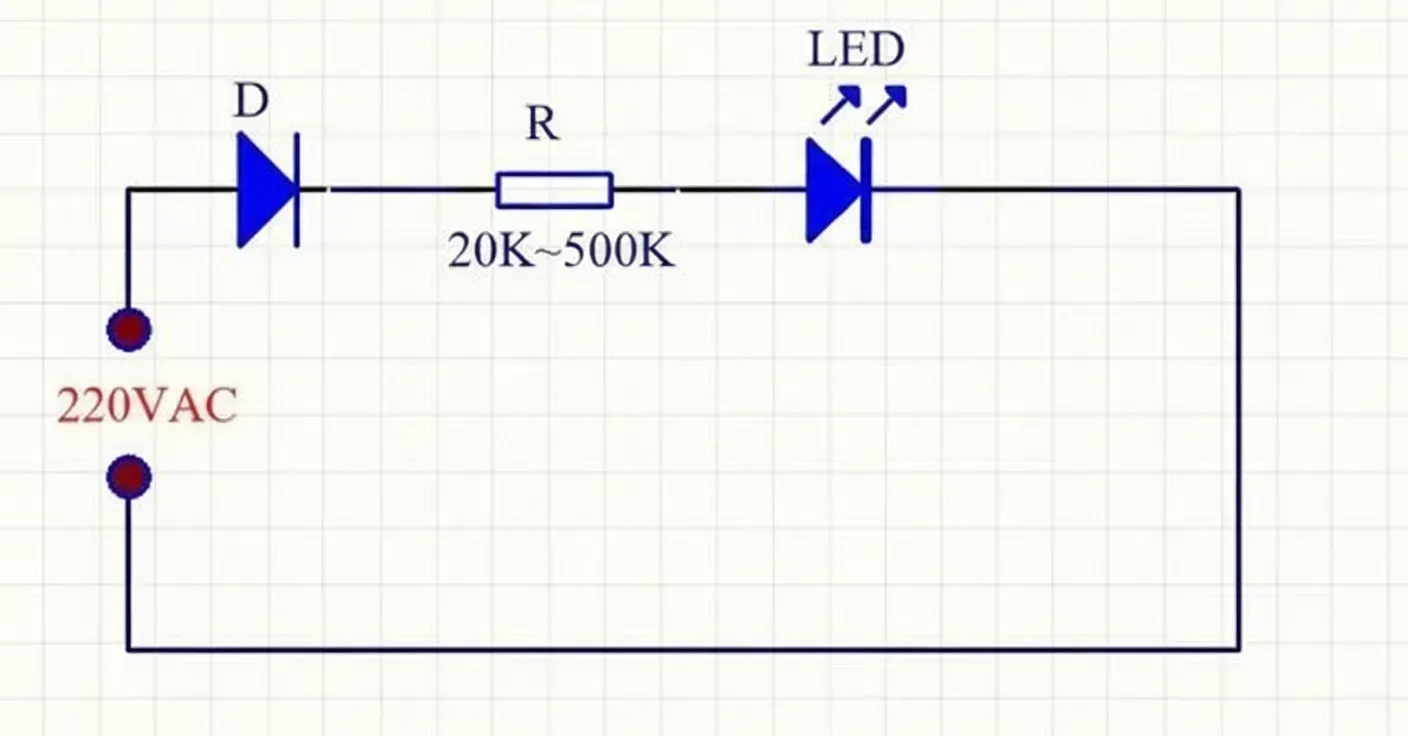
Series and Parallel LED Circuits on 220 V AC
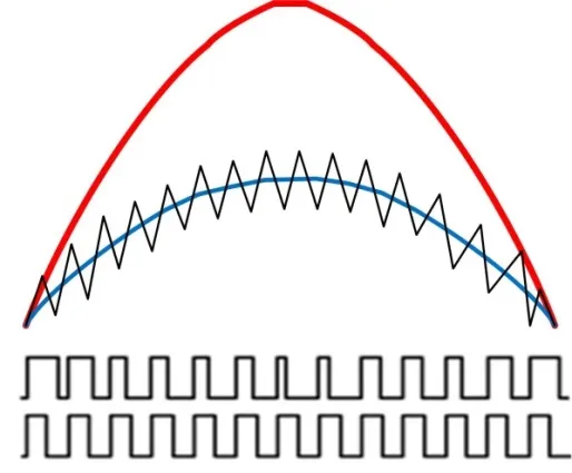
PFC BCM vs CCM Modes Explained: Power Factor Correction in Power Supplies
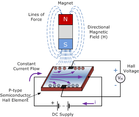
Hall Effect Current Sensors: Optimizing Placement for Noise Immunity in PCB Layouts
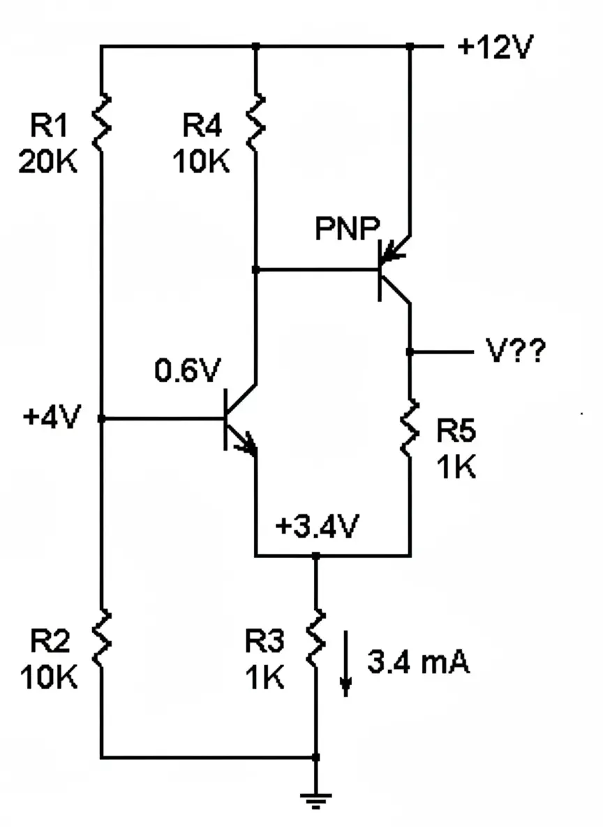
Bipolar Transistor Circuit Analysis
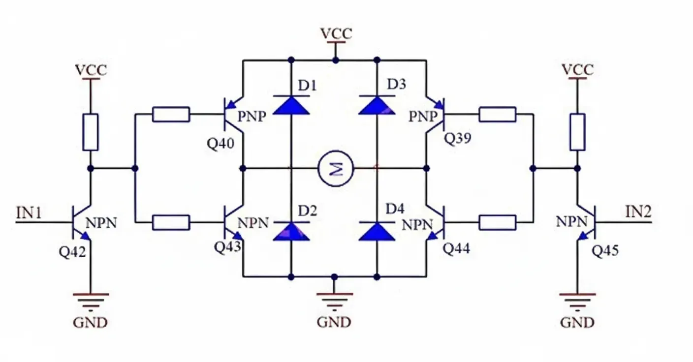
Why MOSFETs Fail in Low-Power BLDC Motors
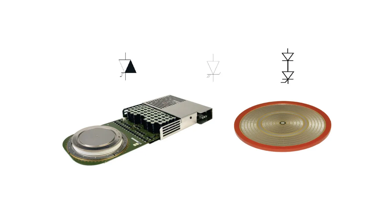
IGCT Overview: Integrated Gate-Commutated Thyristor Technology & Applications
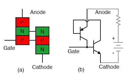
Thyristor SCR Circuit Design: Principles, Considerations & PCB Implementation
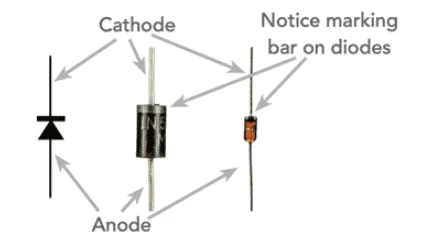
Diode Rectifier Circuit Fundamentals
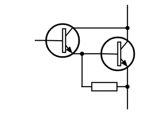
Darlington Transistor Circuit: Key Design Parameters
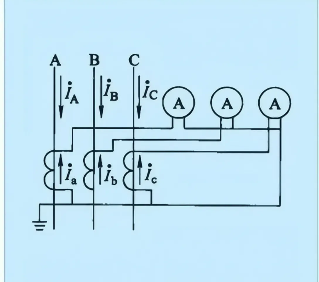
Common Current Transformer Wiring Configurations
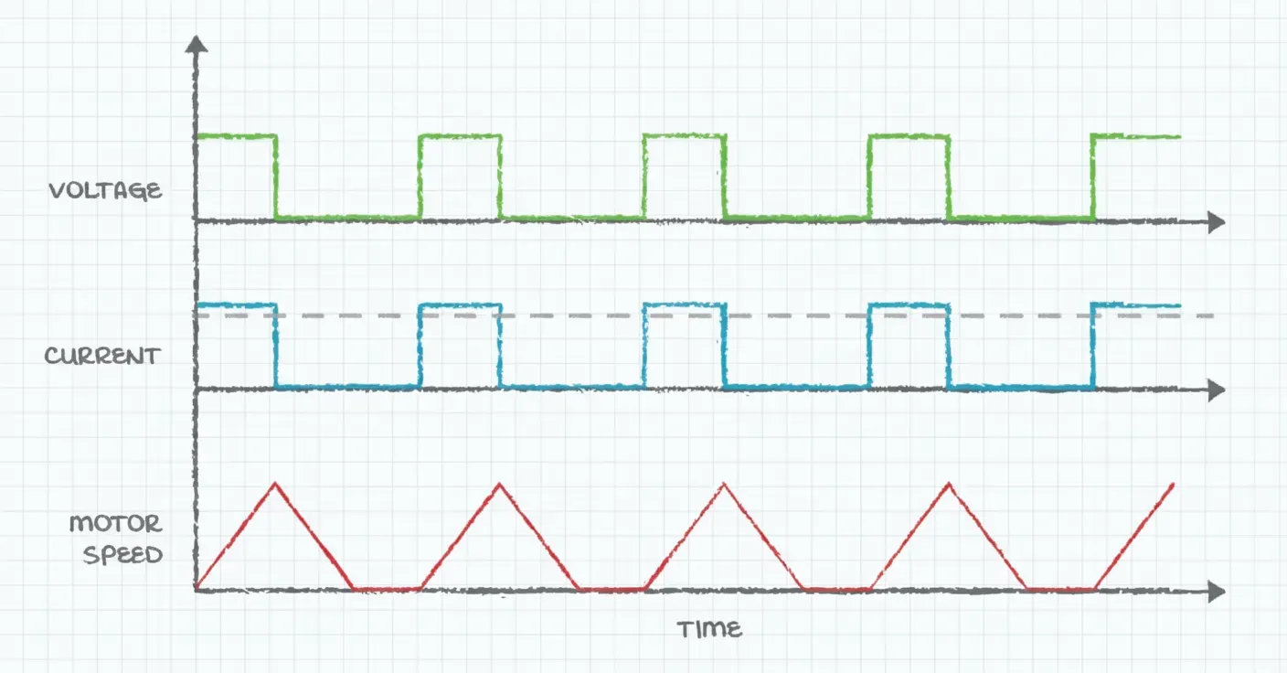
Overcurrent Protection Mechanisms for Power Supplies
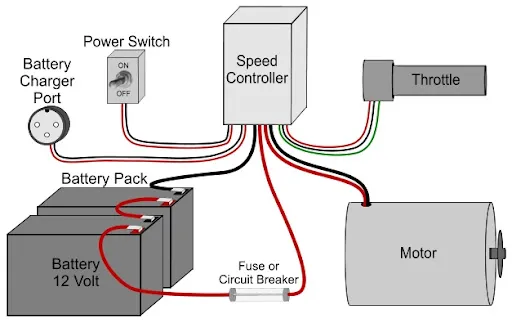
Electric Scooter Battery Charging Circuit
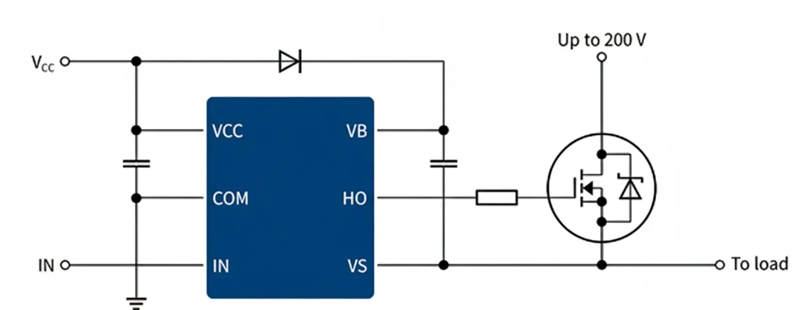
Common MOSFET Circuits for Power Switching
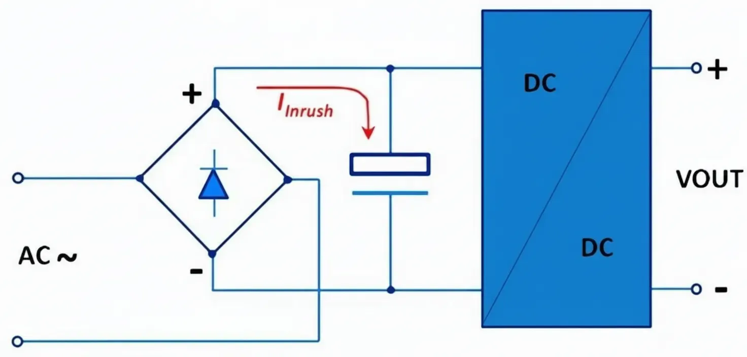
6 Methods to Limit Inrush Current in SMPS
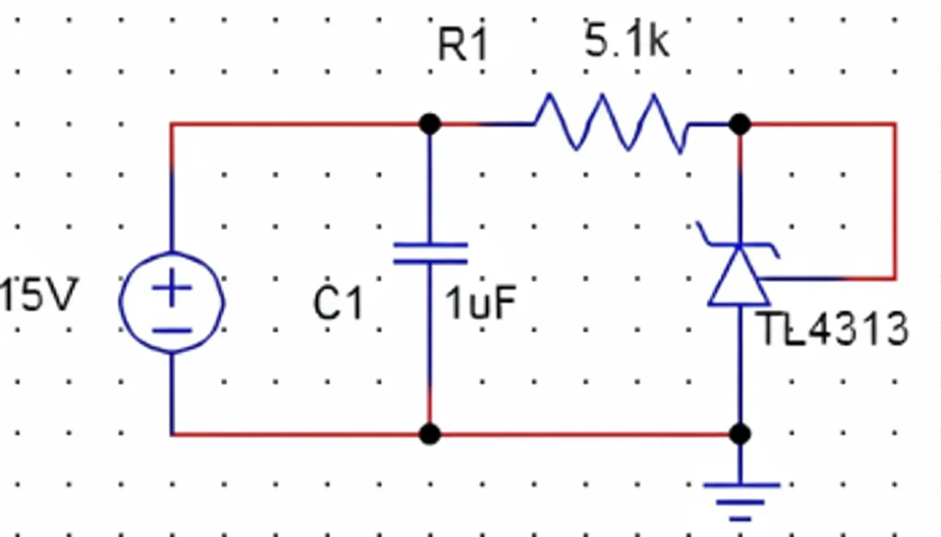
Constant-Current Source Using TL431
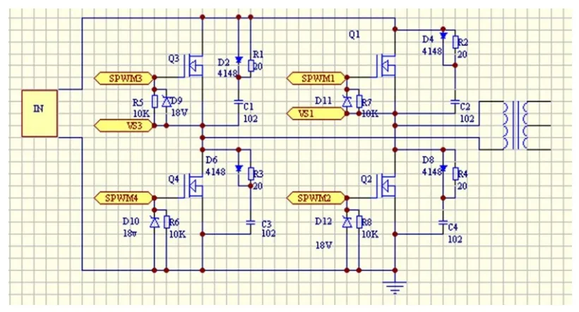
500W Lead-Acid Battery Charging System
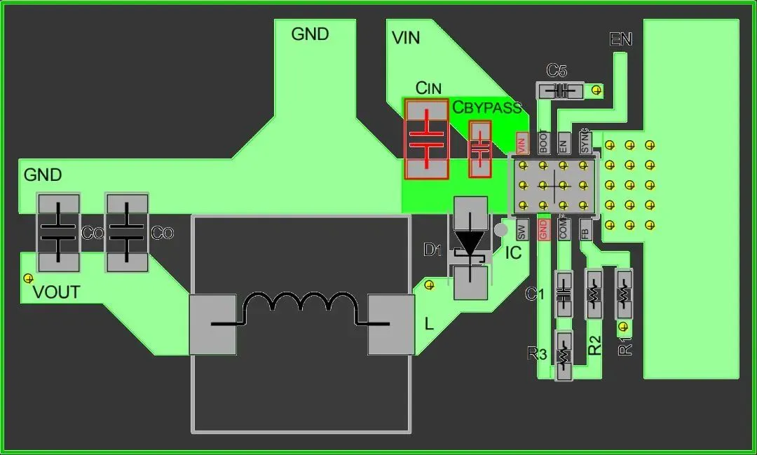
DC-DC Switching Power Supply Design Principles
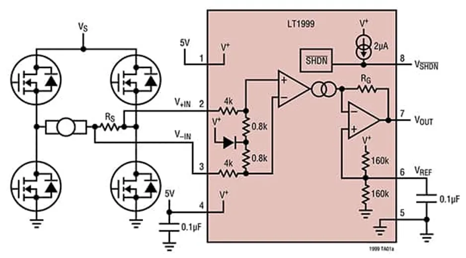
Efficient Bidirectional Current Sensing Techniques