 00:58
Signal Integrity
Signal integrity refers to the preservation of electrical signal quality as it travels through a circuit, ensuring minimal distortion, noise, or timing errors. In high-speed PCB design and electronics, maintaining signal integrity is crucial to prevent issues such as reflections, crosstalk, electromagnetic interference, and signal attenuation that can degrade system performance or cause failures. Engineers and designers often encounter these challenges in applications like data communication systems, automotive electronics, and consumer devices, where even minor signal degradation can lead to unreliable operation or data corruption. This tag page gathers resources focused on signal integrity principles, offering practical guidance for optimizing PCB layouts, selecting appropriate materials, and implementing effective mitigation strategies. For instance, you will find discussions on impedance matching techniques to reduce reflections, proper grounding methods to minimize noise, and simulation tools for predicting signal behavior before prototyping. These insights are particularly valuable for professionals troubleshooting real-world problems or students learning the fundamentals of high-frequency design, helping to bridge theoretical knowledge with hands-on application. By addressing common pitfalls and best practices, the content under the Signal Integrity tag equips you with actionable steps to enhance circuit reliability and efficiency. Whether you are designing for gigabit speeds or ensuring compliance with industry standards, these articles provide in-depth analysis and case studies that can inform your projects. Delving into these topics can refine your approach to electronics design, ultimately leading to more robust and performant systems.
Video Guide
-
00:58
-
 00:53
What is PCB Edge Plating? Benefits, Design Tips & Manufacturing Considerations
-
 00:52
How Many PCB Layers Do Beginners Actually Need?
-
 00:52
Stitching Vias in PCB Design: Essential for EMI Reduction, Heat Management & Signal Integrity
-
 01:09
How Signals Jump Between PCB Layers: Vias Explained
Technical Articles

Drone Area and Airspace Denial Systems

DARPA DRACO Nuclear Rocket Systems: Propulsion Technology and Aerospace Electronics Challenges
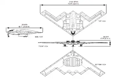
Ghatak UCAV: Technical Overview

PCB Engineering for UAV Inspection, Remote Sensing, and Payload Optimization in Energy, Aerospace, and Emergency Applications

Home Medical Electronics PCB Design for Reliable and Compact Devices
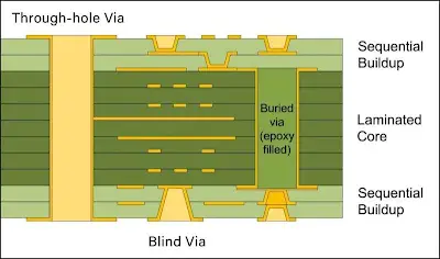
Blind Via Placement Strategies for Optimal Signal Integrity
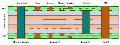
What Are the Benefits of Blind Vias?
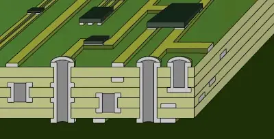
The Essential Role of Blind Vias in HDI PCBs
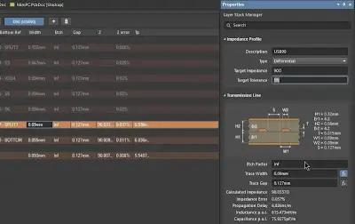
Optimizing PCB Stackup for Differential Impedance Control: A Step by Step Guide
Ultimate Guide to Industrial PCB
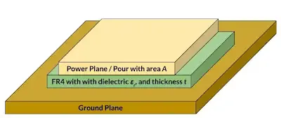
Effective Decoupling Techniques for Multi Layer PCBs: Reducing Noise
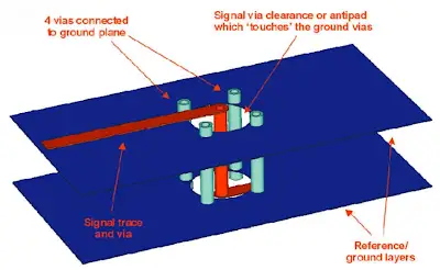
Understanding Power and Ground Planes in Multi Layer PCBs

The Ultimate Guide to Via Stitching in Multi Layer PCBs: Best Practices

Cooperative Guidance for Shipborne Surface-to-Air Missile Systems
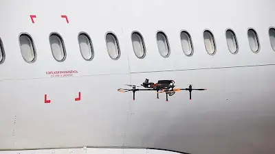
Drones, AI, and Cloud Cut Aircraft Inspection Time

Do DJI Drones Require a Pilot License? Regulations, Compliance, and Electronics Implications

5G Applications for Unmanned Aerial Vehicles: Connectivity, Use Cases, and PCB Challenges

C919 Airliner: Development Challenges, Technical Route, and Avionics Electronics Insights
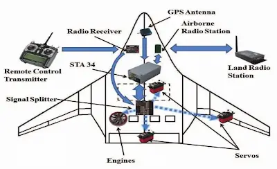
Drone gyroscopes and control system principles