 00:58
Signal Integrity
Signal integrity refers to the preservation of electrical signal quality as it travels through a circuit, ensuring minimal distortion, noise, or timing errors. In high-speed PCB design and electronics, maintaining signal integrity is crucial to prevent issues such as reflections, crosstalk, electromagnetic interference, and signal attenuation that can degrade system performance or cause failures. Engineers and designers often encounter these challenges in applications like data communication systems, automotive electronics, and consumer devices, where even minor signal degradation can lead to unreliable operation or data corruption. This tag page gathers resources focused on signal integrity principles, offering practical guidance for optimizing PCB layouts, selecting appropriate materials, and implementing effective mitigation strategies. For instance, you will find discussions on impedance matching techniques to reduce reflections, proper grounding methods to minimize noise, and simulation tools for predicting signal behavior before prototyping. These insights are particularly valuable for professionals troubleshooting real-world problems or students learning the fundamentals of high-frequency design, helping to bridge theoretical knowledge with hands-on application. By addressing common pitfalls and best practices, the content under the Signal Integrity tag equips you with actionable steps to enhance circuit reliability and efficiency. Whether you are designing for gigabit speeds or ensuring compliance with industry standards, these articles provide in-depth analysis and case studies that can inform your projects. Delving into these topics can refine your approach to electronics design, ultimately leading to more robust and performant systems.
Video Guide
-
00:58
-
 00:53
What is PCB Edge Plating? Benefits, Design Tips & Manufacturing Considerations
-
 00:52
How Many PCB Layers Do Beginners Actually Need?
-
 00:52
Stitching Vias in PCB Design: Essential for EMI Reduction, Heat Management & Signal Integrity
-
 01:09
How Signals Jump Between PCB Layers: Vias Explained
Technical Articles

What Is an Eye Diagram and How to Read One?

Critical PCB Copper Pour Guidelines: When Copper Pour Can Do More Harm Than Good

Multilayer PCB Impedance Control: Design Rules for 4-Layer to 8-Layer PCBs

PCB Design Guidelines: Key Routing and Layout Considerations

Complete Guide to Power-Rail Ripple and Noise Testing: From Principles to Practice

6-Layer PCB vs 4-Layer PCB: When Should You Use Six Layers?

High-Speed Interface Routing on 8-Layer PCBs: DDR, PCIe and USB Design Considerations

Single-Layer vs Multilayer PCB: Key Differences in Design and Applications

8-Layer PCB vs 6-Layer PCB: When Should You Choose Eight Layers?

High-Speed Interface Routing on 6-Layer PCBs: DDR, USB and PCIe Design Considerations

Press-Fit Interconnects for Electronics: Principles, Materials, Process, and Controls

Key Manufacturing Technologies for Drone PCBs
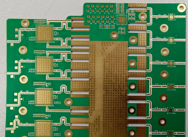
From Signal Frequency to Signal Integrity: What Is the Fundamental Difference Between High-Frequency and High-Speed PCBs?
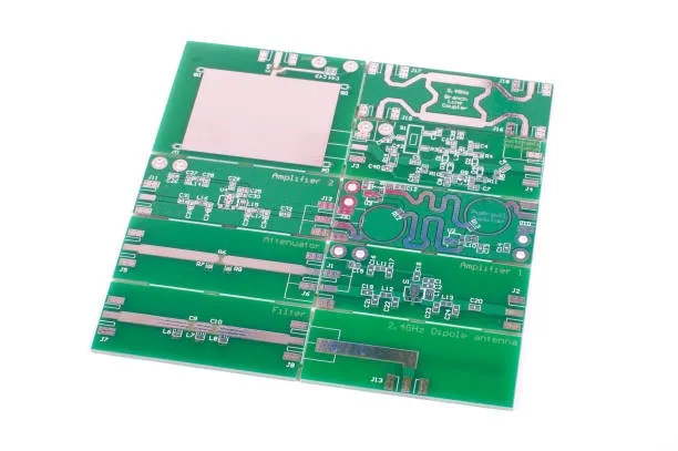
Mastering Rogers PCB: A Comprehensive Resource for High-Speed Design, Applications, and Fabrication
Enhancing USB Performance: A Guide to Optimal PCB Layout and Signal Integrity
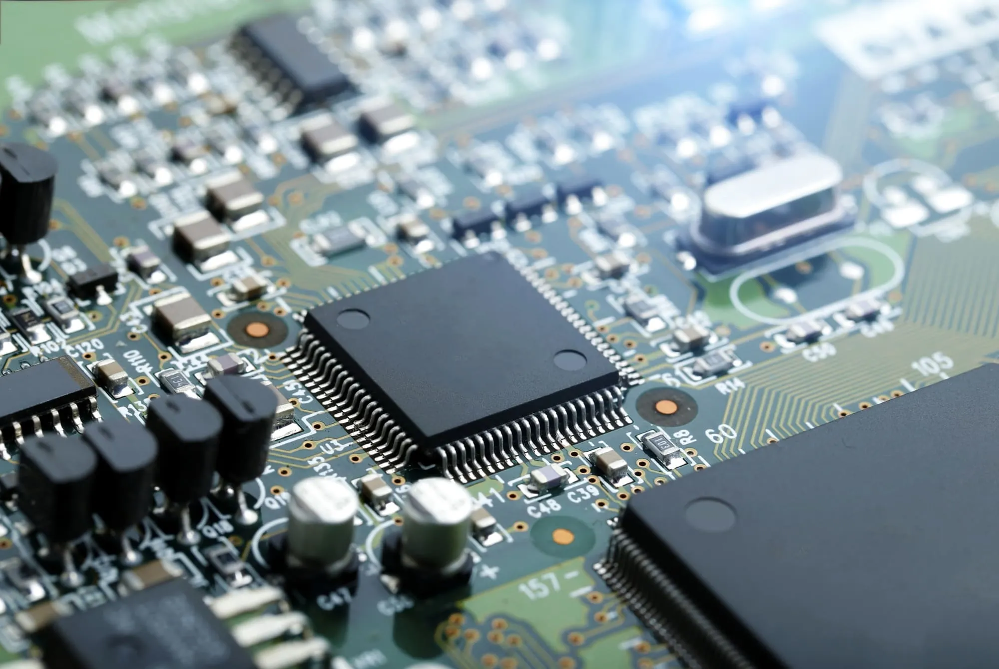
Build Your Own AI Accelerator: A Hobbyist's Custom PCB Guide
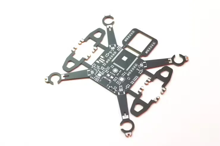
Designing High-Performance Drone Flight Controller PCBs: A Comprehensive Guide
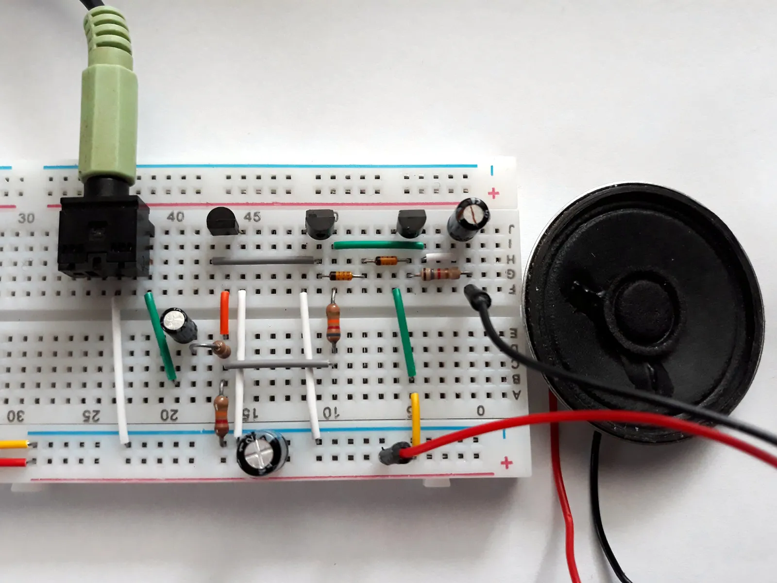
Fast & Efficient Audio Amplifier PCB Prototyping Methods
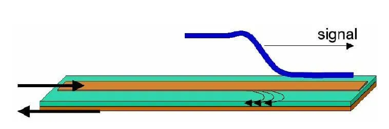
DIY PCB Impedance Measurement: A Home Lab Guide