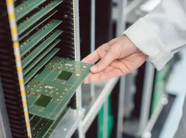
 00:58
Signal Integrity
Signal integrity refers to the preservation of electrical signal quality as it travels through a circuit, ensuring minimal distortion, noise, or timing errors. In high-speed PCB design and electronics, maintaining signal integrity is crucial to prevent issues such as reflections, crosstalk, electromagnetic interference, and signal attenuation that can degrade system performance or cause failures. Engineers and designers often encounter these challenges in applications like data communication systems, automotive electronics, and consumer devices, where even minor signal degradation can lead to unreliable operation or data corruption. This tag page gathers resources focused on signal integrity principles, offering practical guidance for optimizing PCB layouts, selecting appropriate materials, and implementing effective mitigation strategies. For instance, you will find discussions on impedance matching techniques to reduce reflections, proper grounding methods to minimize noise, and simulation tools for predicting signal behavior before prototyping. These insights are particularly valuable for professionals troubleshooting real-world problems or students learning the fundamentals of high-frequency design, helping to bridge theoretical knowledge with hands-on application. By addressing common pitfalls and best practices, the content under the Signal Integrity tag equips you with actionable steps to enhance circuit reliability and efficiency. Whether you are designing for gigabit speeds or ensuring compliance with industry standards, these articles provide in-depth analysis and case studies that can inform your projects. Delving into these topics can refine your approach to electronics design, ultimately leading to more robust and performant systems.
Video Guide
-
00:58
-
 00:53
What is PCB Edge Plating? Benefits, Design Tips & Manufacturing Considerations
-
 00:52
How Many PCB Layers Do Beginners Actually Need?
-
 00:52
Stitching Vias in PCB Design: Essential for EMI Reduction, Heat Management & Signal Integrity
-
 01:09
How Signals Jump Between PCB Layers: Vias Explained
Technical Articles

Why Backdrill Stubs Can Still Be Too Long After the Layer Pair Is Correct
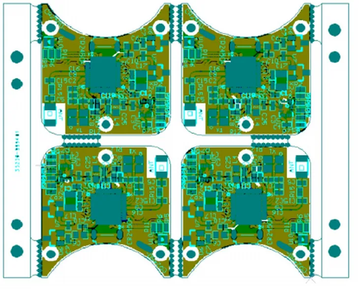
Why a Pick-and-Place Machine Can Still Fail Fiducial Recognition When Three Marks Are Present
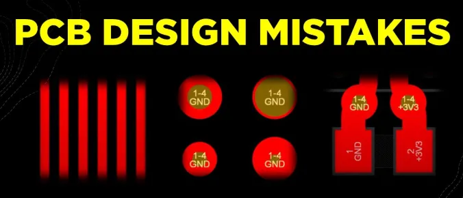
The Ten Most Common Beginner Mistakes in PCB Layout
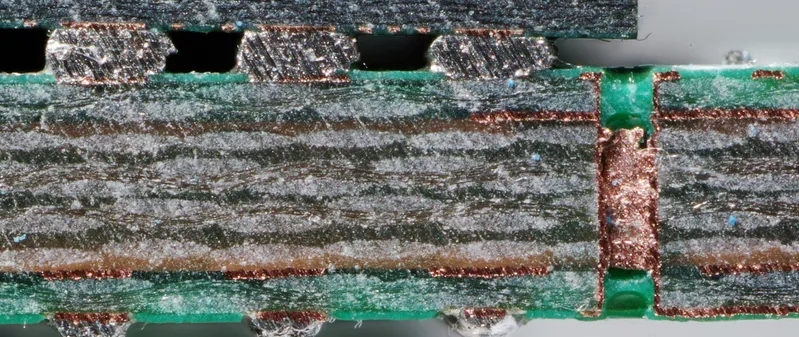
Small Anti-Pads Can Cause Unconnected Vias to Short
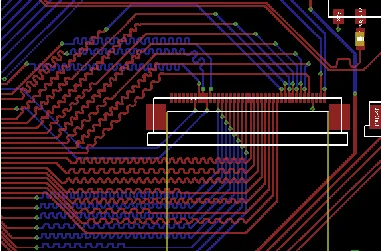
FR4 PCB Differential Pair Routing: Spacing and Length Matching
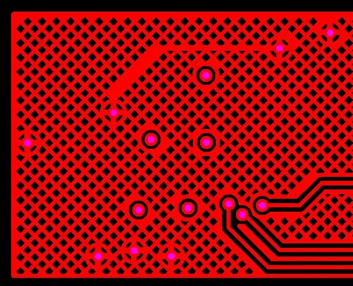
Solid Copper or Hatched Copper on PCBs and FPCs: Key Design Considerations
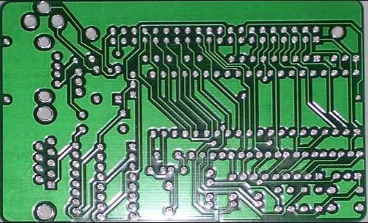
Why Does a PCB Designed for 50 Ω Measure 53 Ω After Manufacturing?
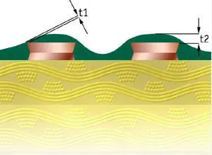
PCB Solder Mask Thickness: When It Is Too Thick, It Becomes Armor; When It Is Too Thin, It Creates Hidden Risks
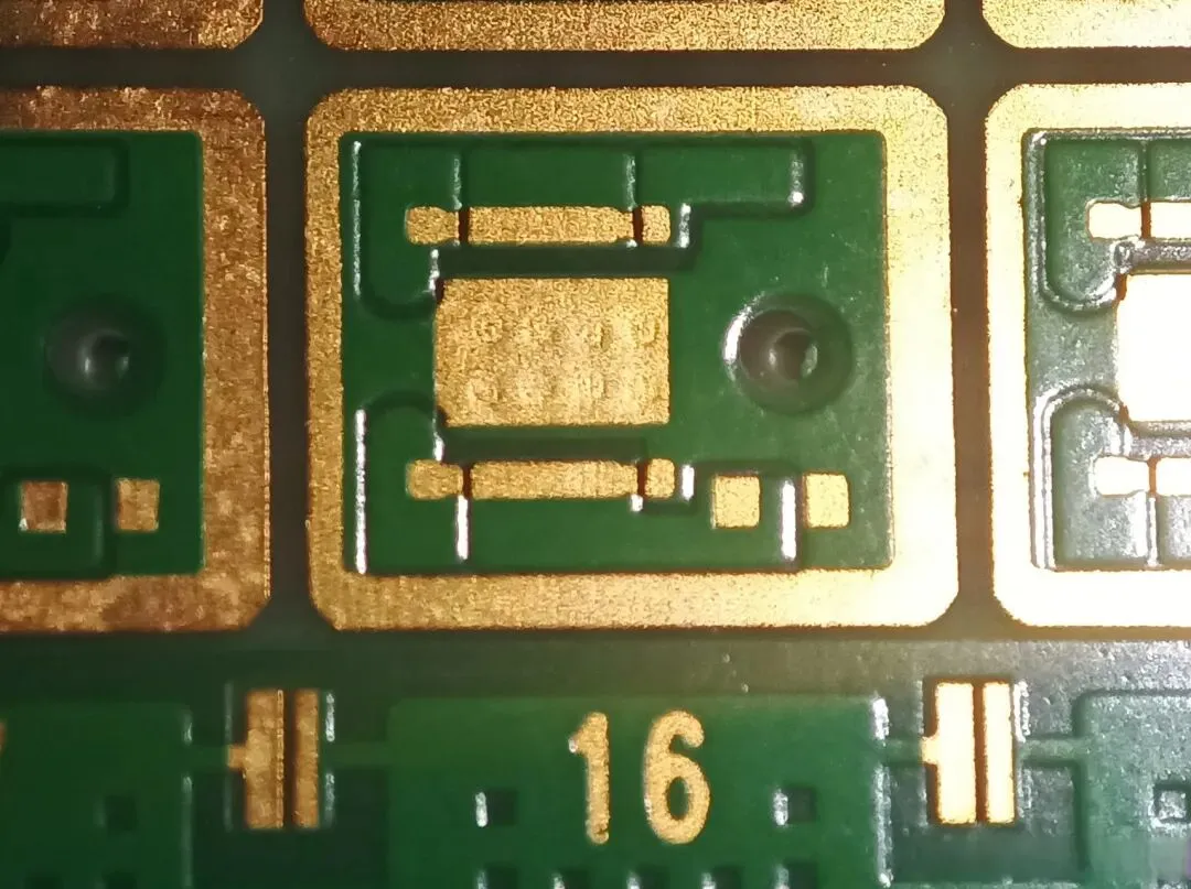
Via-in-Pad: Three Critical Manufacturing Risks and Four Valid Use Cases
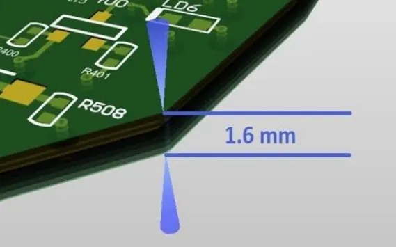
Why Does a 1.6 mm PCB Measure Only 1.4 mm? The Engineering Reality Behind PCB Thickness Calculations
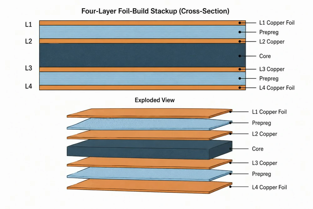
Multilayer PCB Construction Explained: Layers, Cores, Prepreg and Copper Foil
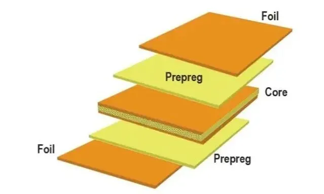
What Do 7628, 1080, and 2116 Mean in a PCB? Understanding These Numbers Means Understanding the Stack-Up

What Roles Does Palladium Play in PCB Manufacturing?

PCB Design Assumptions That Can Lead to Costly Rework

How AI Can Assist Multilayer PCB Routing and Design
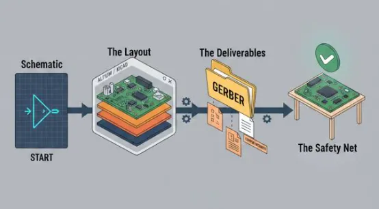
Multilayer PCB Manufacturing Tolerances: Layer Registration and Alignment
From Hardware to Chips: Exploring the Underlying Logic of Hardware Engineering
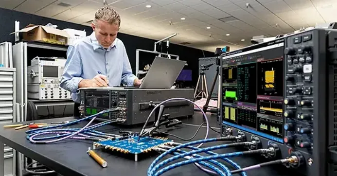
Time-Interleaved Sampling: A Key Technology in High-End Oscilloscopes
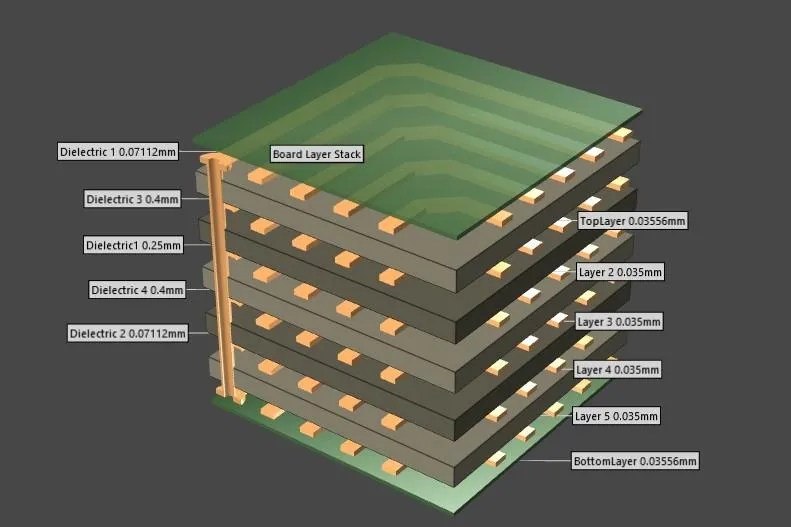
Multilayer PCB Layout Guidelines: Routing, Planes and Layer Management