Why Do FPC Pads Peel Off During SMT Assembly?
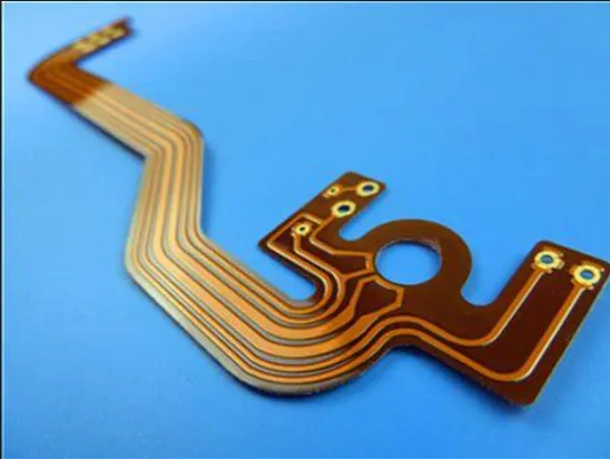
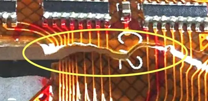
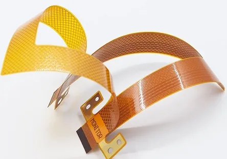
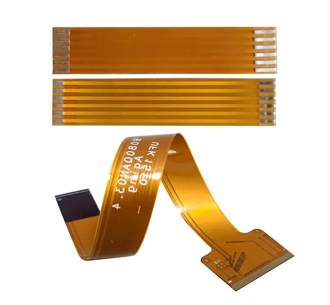
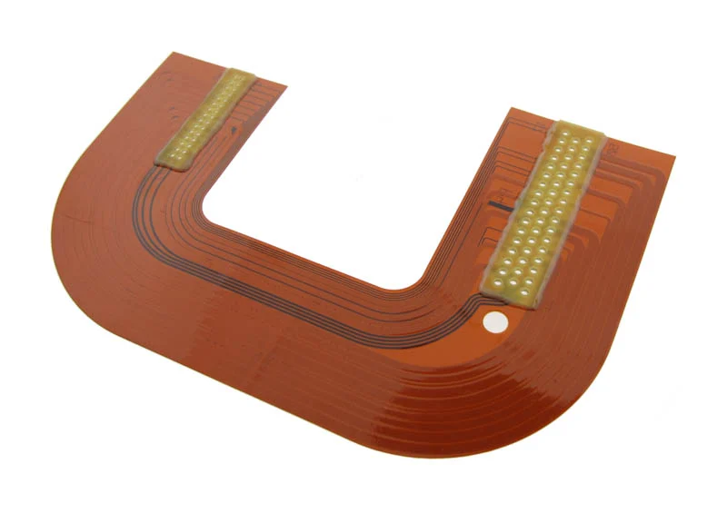
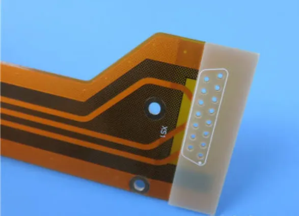
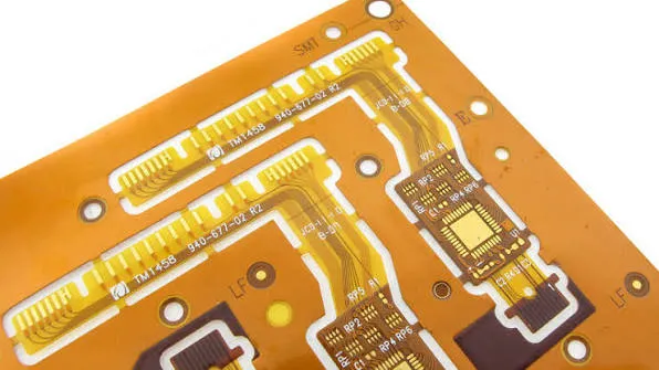
FPC pad peeling is a frequent flexible PCB SMT failure. Factories stop it by enforcing 0.10–0.15 mm coverlay overlap, thicker copper, and adhesion control before reflow.
Printed circuit boards (PCBs) form the backbone of modern electronics, serving as the essential platform for connecting components in devices ranging from smartphones to industrial machinery. In our PCB Types category, we delve into the diverse array of PCB designs and configurations available today, exploring how each type addresses specific engineering challenges and performance needs. Whether you are a hobbyist building a prototype or an engineer optimizing for high-frequency applications, understanding these variations is crucial for selecting the right board for your project. The scope of PCB Types encompasses everything from single-layer boards ideal for simple circuits to complex multilayer designs that support advanced signal integrity and thermal management. We cover rigid, flexible, and rigid-flex PCBs, along with specialized options like high-density interconnect (HDI) and metal-core boards used in power electronics. This category highlights the practical value of these choices, such as enhancing durability in automotive systems or enabling compact designs in wearable technology. By examining real-world applications, from consumer gadgets to aerospace equipment, readers gain insights into how PCB selection influences reliability, cost efficiency, and overall system performance. Our articles provide comprehensive guides on evaluating PCB types for different environments, tutorials on assembly techniques, and best practices for material selection to avoid common pitfalls. We also share expert insights into emerging trends, such as eco-friendly substrates and advancements in 5G-compatible boards. These resources equip professionals and enthusiasts with the knowledge to innovate and troubleshoot effectively. As you navigate through the posts in this category, you will discover strategies to apply in your own designs, fostering a deeper appreciation for the technical nuances that drive electronic innovation.
FPC pad peeling is a frequent flexible PCB SMT failure. Factories stop it by enforcing 0.10–0.15 mm coverlay overlap, thicker copper, and adhesion control before reflow.
Factory limits for FPC minimum trace width spacing: 50/50 µm on 18 µm copper, 40/40 µm on 12 µm copper. How etch undercut, compensation, and laminate movement set flexible PCB line spacing in real production.
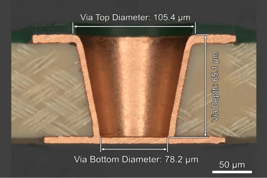
Factory standard for FPC laser drilling minimum hole size is 50 µm on UV stations. See how material thickness, UV vs CO₂, and DFM rules control flex PCB microvia size and yield in real production.
Factory view on FPC copper crack after repeated flexing. How cyclic strain, copper thickness, and ED vs RA foil drive flexible PCB copper fatigue, plus the CAM and process fixes that stop it in production.
FPC curling and flexible PCB warpage come from residual stress, uneven copper and lamination. See how factories control copper balance, materials and process to keep flex flat.
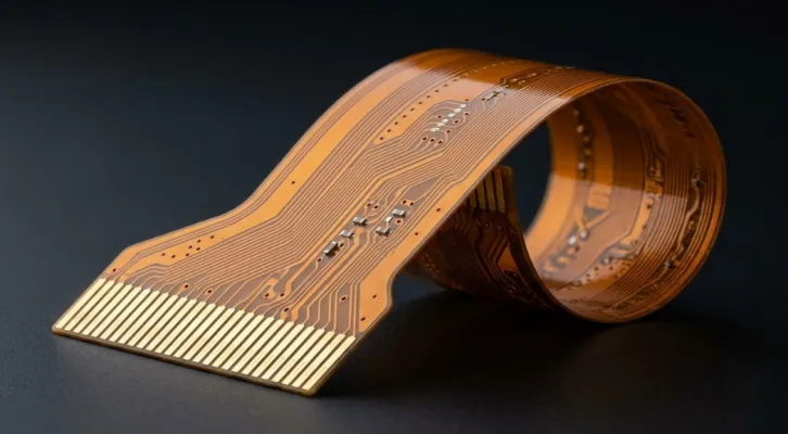
Practical limits on flexible PCB bending cycles and FPC flex life. Covers RA vs ED copper, bend radius effects, dynamic test methods, and cycle targets for wearables, camera modules, and foldables.
Copper fatigue, tight bend radius, and PI damage cause most FPC bending cracks. Learn the real design and stack-up factors behind flexible PCB bending failure and how to raise cycle life.
Practical guidance on flexible PCB copper thickness selection. How 1/3 oz, 1/2 oz and 1 oz copper affect bend fatigue, current capacity and impedance in dynamic vs static FPC applications.
PI vs FR4 stiffener FPC, flex PCB reinforcement comparison: Expert manufacturing advice on thickness, strength, cost, yield, and industrial selection logic for flex PCB stiffeners.
FPC 14pcs vs 30pcs panel flex PCB panel size tradeoff: Expert factory advice on yield, cost, stability, and when to choose large vs small panels for flexible circuit orders.
Discover everything about HDI PCB in this complete guide. Learn the fundamentals of HDI PCB Design, Manufacturing, Assembly, and Application along with benefits, trends, and best practices.
PTFE PCBs provide high reliability for aerospace and defense in extreme environments like high vibrations and thermal cycles. Details material properties, applications in radar and satellites, military standards compliance, and manufacturing practices for engineers designing reliable boards.