00:53
Impedance Control
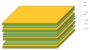
Impedance control is a critical aspect of printed circuit board (PCB) design, ensuring that signal traces maintain consistent electrical characteristics to prevent distortions, reflections, and data loss in high-speed applications. This tag encompasses a range of topics related to managing characteristic impedance in PCBs, from fundamental concepts to advanced implementation strategies. For engineers and designers searching for impedance control solutions, understanding this principle is essential for optimizing performance in systems like telecommunications, computing, and automotive electronics, where signal integrity directly impacts reliability and efficiency. At its core, impedance control involves precise calculation and control of trace geometry, dielectric materials, and layer stackups to match the required impedance values, typically 50 ohms for RF signals or 100 ohms for differential pairs. Practical applications include high-speed interfaces such as USB, PCIe, and Ethernet, where mismatches can lead to electromagnetic interference or signal degradation. Best practices start with accurate simulations using tools like field solvers to predict impedance, followed by selecting appropriate trace widths, spacing, and via configurations. For instance, maintaining uniform trace routing and incorporating ground planes can minimize variations, while regular testing with time-domain reflectometry ensures compliance during prototyping. Professionals often encounter challenges like manufacturing tolerances or environmental factors affecting impedance, which this tag addresses through case studies and troubleshooting guides. By delving into these resources, you can gain actionable insights to refine your designs, such as integrating controlled impedance into multilayer boards or adapting to flexible PCBs. Exploring the articles under this tag provides in-depth discussions on these techniques, helping you apply proven methods to your projects and achieve robust, high-performance electronics.
Video Guide

Technical Articles
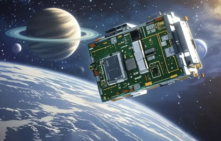
Advanced PCB Layout Techniques for Spacecraft Electronics: Minimizing Noise and Interference
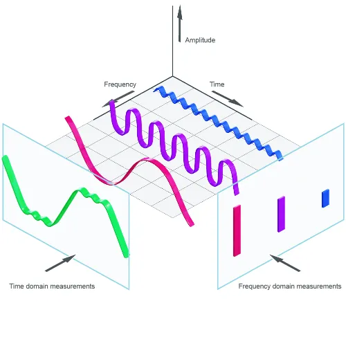
Relationship Between Frequency and Time Domains
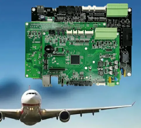
Signal Integrity in the Sky: Optimizing PCB Layout for Avionics Systems
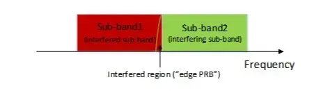
Role of OFDM Waveforms in 5G
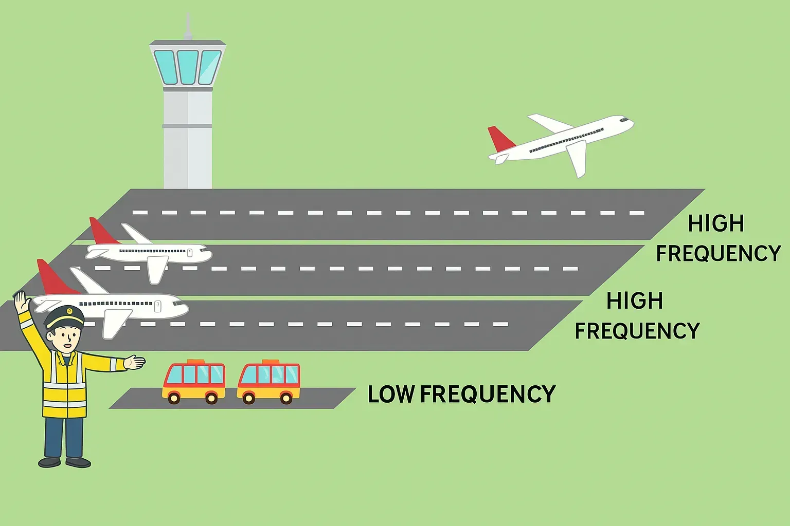
Basics of Baseband and Radio Frequency
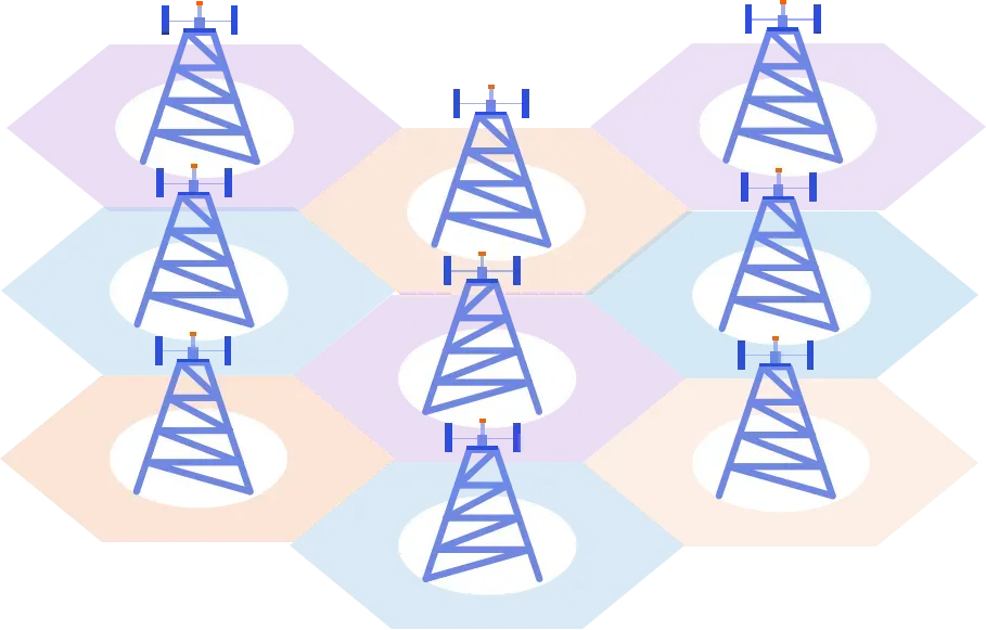
Why Mobile Phone Signals Weaken: PCB Design, RF Performance, and Manufacturing Considerations
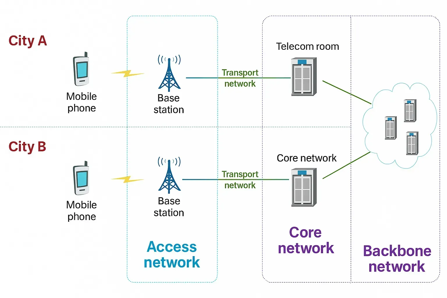
5G Fronthaul, Midhaul, and Backhaul: PCB Design Challenges for High-Speed Optical Transport and Antenna Integration
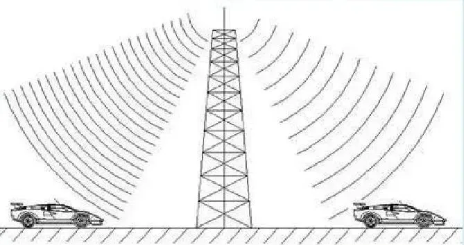
Air-to-Ground Communication: Channel Selection
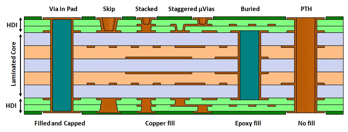
The Ultimate Guide to Via Design in High-Tg PCBs
Boosting Signal Integrity: How CEM-3 PCBs Excel in High-Frequency Designs
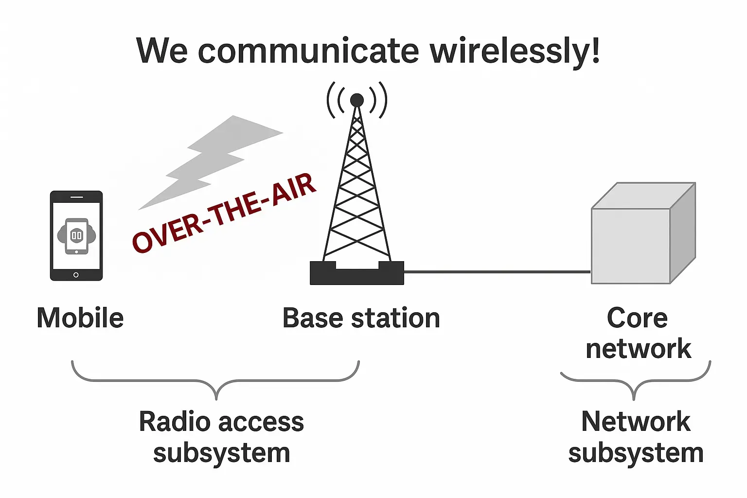
What Is the Air Interface? 5G Network Options
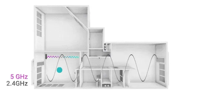
5G mmWave: Benefits and Drawbacks
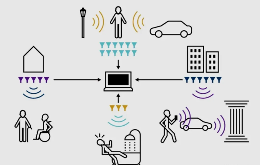
When Will B5G/6G Be Deployed? 6G Sensing Technologies

Improving 5G User Experience and Offload Strategies
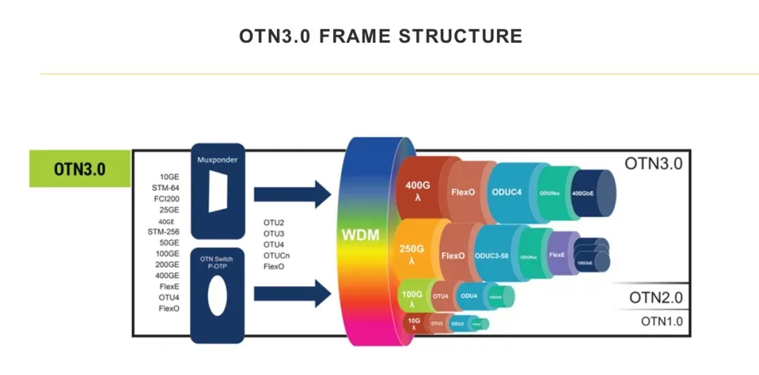
OTN vs FlexE for 5G Network Slicing

How 5G Mobility Handovers Affect Applications
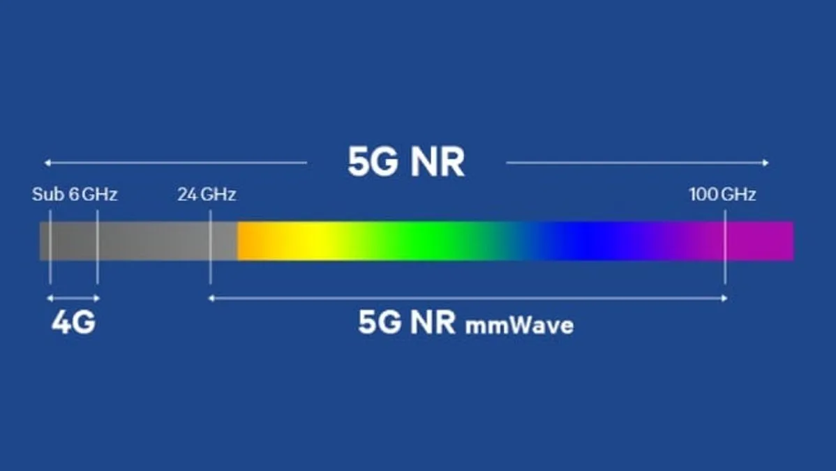
5G Millimeter-Wave Standardization and Spectrum Use
Small 5G Base Stations: PCB Design, Manufacturing, and Low-Power Optimization for Dense Network Deployment
Sequential Lamination for Rigid-Flex PCBs: Design Considerations and Manufacturing Challenges