PCB Manufacturing Defects
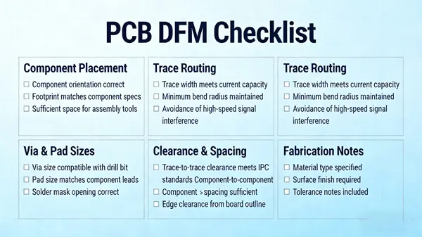
PCB manufacturing defects can significantly impact the performance, reliability, and longevity of electronic devices, making it essential for engineers, designers, and manufacturers to understand and address them effectively. This tag, PCB Manufacturing Defects, serves as a comprehensive resource hub for professionals and enthusiasts seeking to identify, prevent, and resolve common issues that arise during the printed circuit board production process. Whether you are troubleshooting a faulty prototype or optimizing a high-volume assembly line, the articles gathered here provide practical guidance on spotting defects early and implementing corrective measures to ensure high-quality outcomes. Common defects include soldering issues like bridging or cold joints, which often stem from improper temperature control or flux application, as well as trace delamination caused by material inconsistencies or environmental stresses. Other prevalent problems encompass via failures, where plating voids lead to connectivity breakdowns, and component misalignment due to stencil inaccuracies. By exploring these topics, you gain actionable insights into root cause analysis techniques, such as using X-ray inspection or automated optical inspection (AOI) tools, which help pinpoint flaws without destructive testing. Best practices highlighted in our content emphasize design for manufacturability (DFM) principles, like incorporating adequate clearances and selecting robust materials, to minimize defects from the outset. For those dealing with real-world challenges, the tag offers case studies and step-by-step tutorials on rework strategies, including safe desoldering methods and conformal coating repairs. Understanding these defects not only reduces scrap rates and production costs but also enhances product safety and compliance with industry standards like IPC-A-610. Dive into the related articles to equip yourself with the knowledge needed to elevate your PCB projects, from hobbyist builds to industrial applications, ensuring fewer failures and more reliable electronics.
Technical Articles

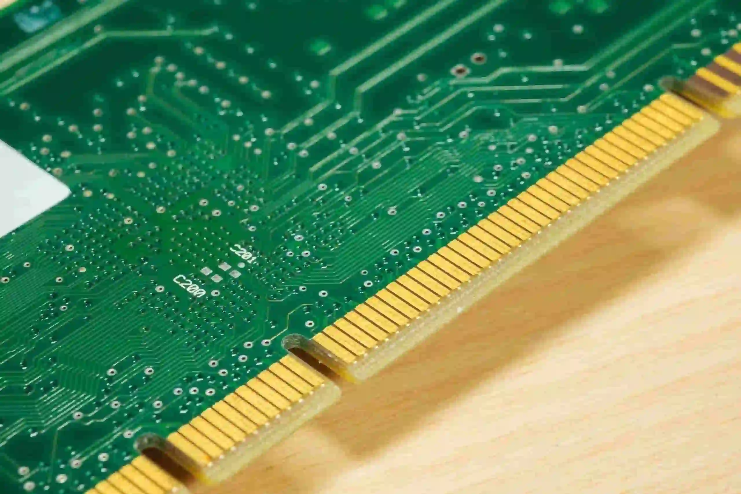
How to Address Discoloration and Oxidation on PCB Gold Fingers

Plug-and-Print or Plug First, Then Print? Comparing PCB Via-Plugging Processes

What Causes PCB Delamination? A Practical Analysis of Mechanical, Thermal, and Material-Related Factors

Can Laser Forming Cause Defects in FPCs?

How to Control V-Cut Depth to Prevent Board Breakage and Excessive Burrs

How to Prevent Ink Residue Inside NPTH Holes

IPC Class 3 vs. Class 2: Key Differences and Detectability
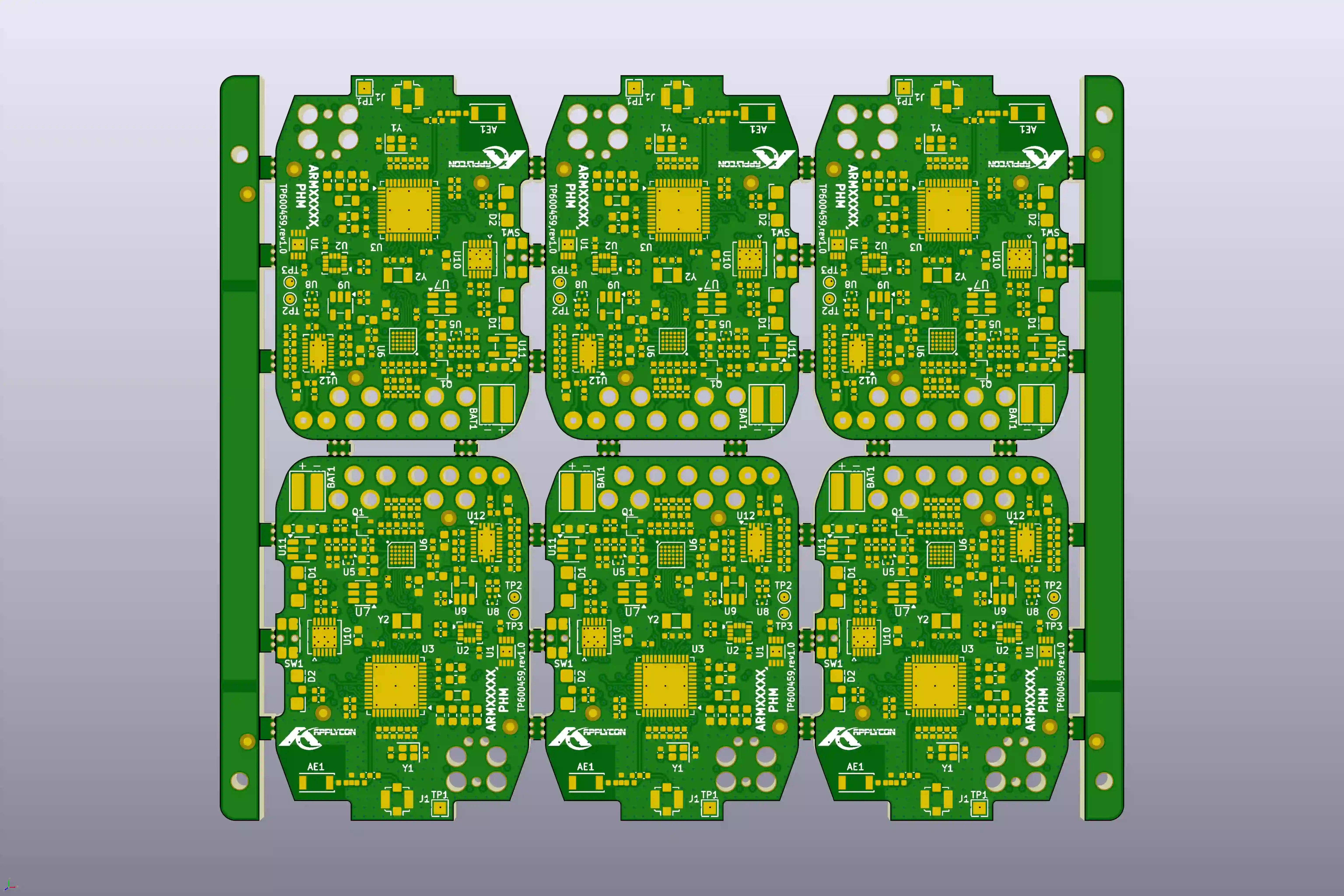
How to Avoid Common Solder Mask & Stackup Issues in 6-Layer HDI PCBs

8-Layer FR-4 PCB with Blind Vias: Solder Mask Openings, Via Plugging and V-CUT Clearance Issues During CAM Review

PCB CAM Review: Fix V-Cut & Via Spacing to Avoid Delays
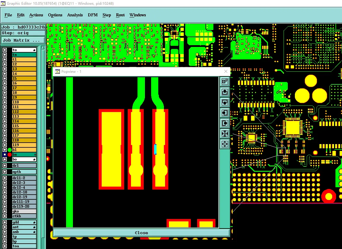
Why Your 20 Layer PCB Fails CAM: Trace Space & Impedance Fixes
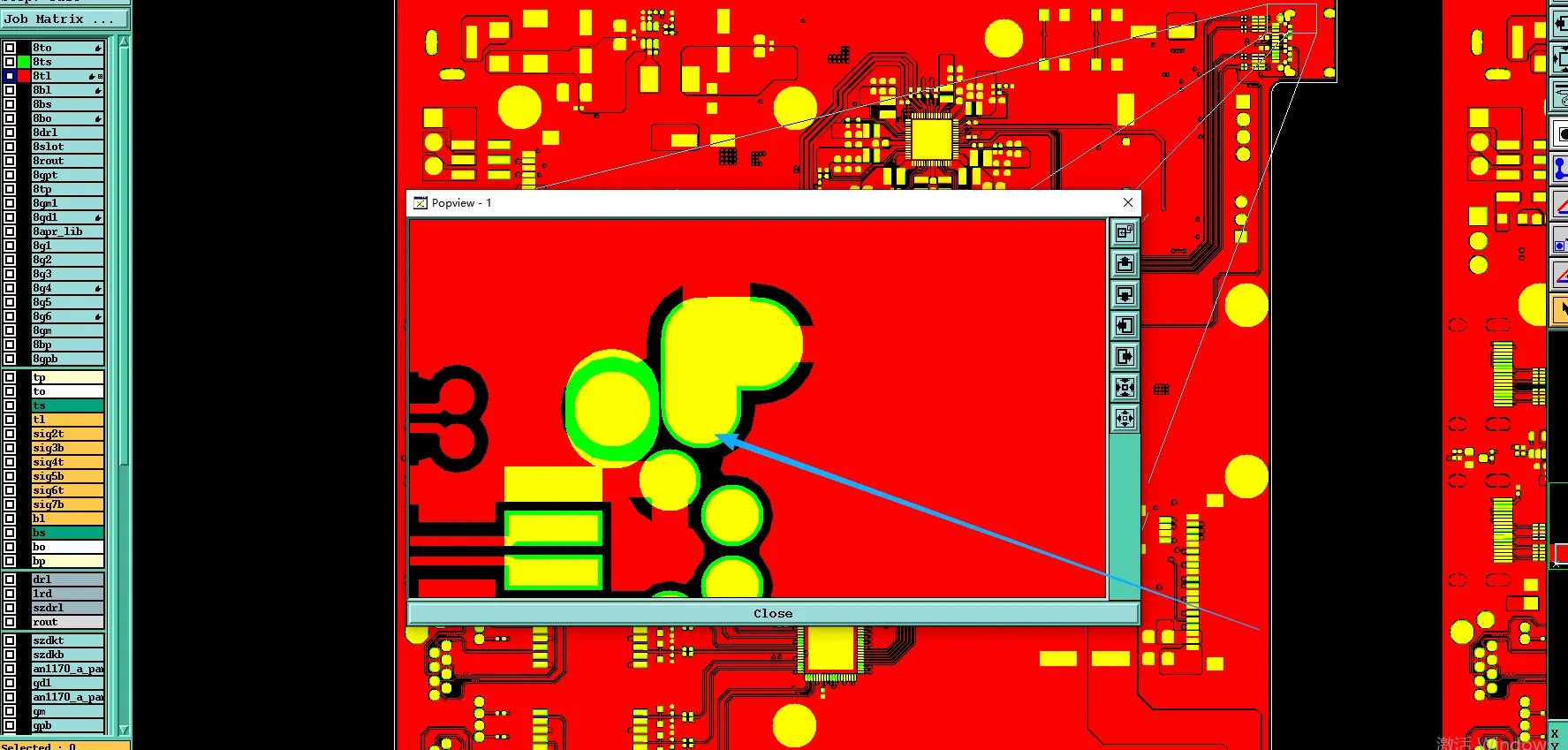
How to Fix Tight Pad Spacing and Impedance EQs in 8-Layer PCB CAM Review
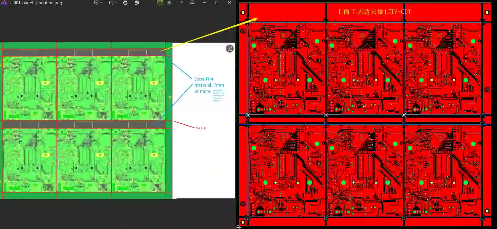
How to Solve 2-Layer PCB CAM Issues Before Manufacturing
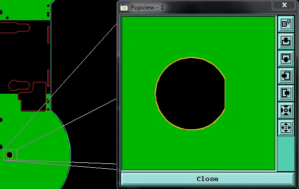
How to Avoid Countersink & Copper Issues in 3mm Thick FR4 PCB Manufacturing
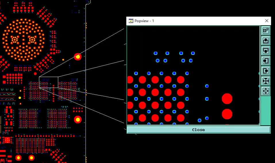
Fixing 18-Layer PCB Risks: The Power of PCB CAM Review
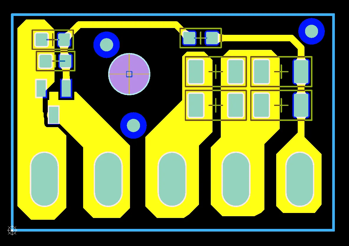
Common 1 Layer FR4 PCB EQ Issues: How Manufacturers Review Gerber Files
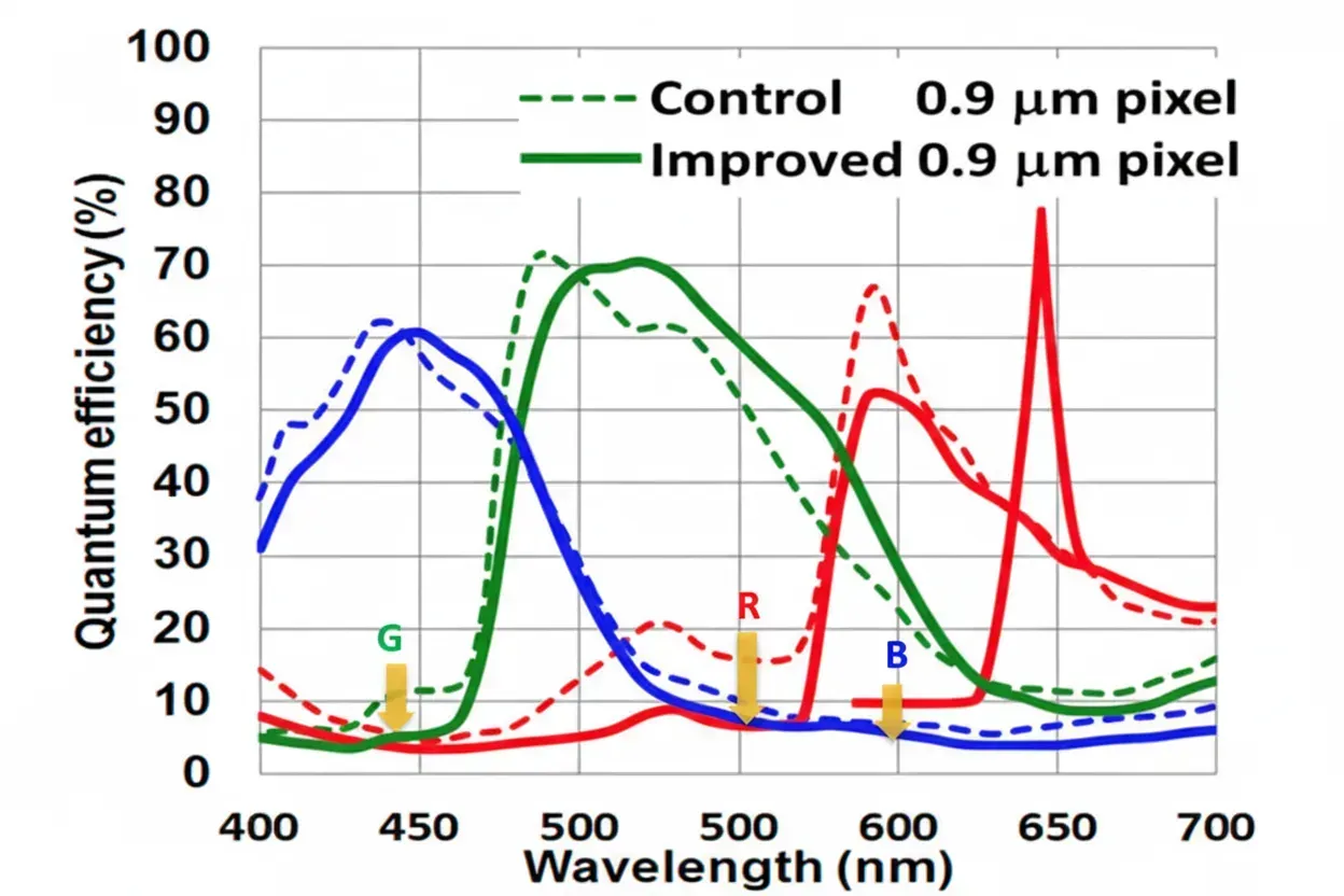
Quantum Efficiency Spectrum of CMOS Image Sensors
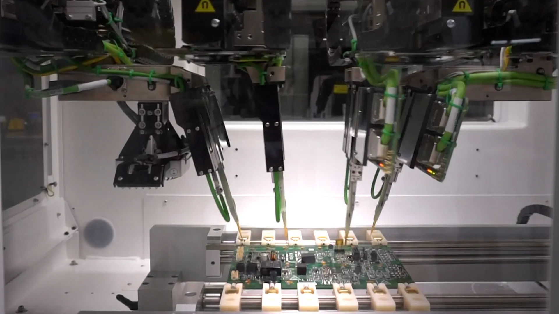
Boosting PCB Reliability: How Flying Probe Testing Minimizes Manufacturing Defects