 00:56
PCB Materials
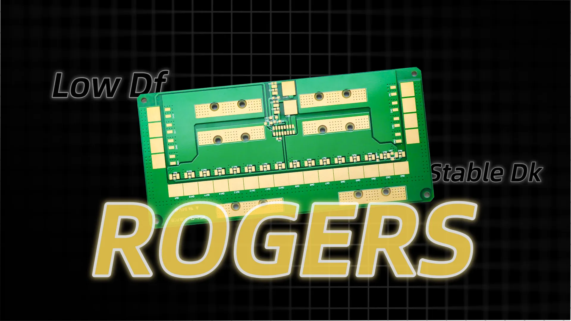
Printed circuit boards (PCBs) form the backbone of modern electronics, and the choice of materials directly influences performance, reliability, and cost. The PCB Materials tag on this blog gathers in-depth resources that explore the various substrates, laminates, and coatings essential for PCB design and manufacturing. Whether you are an engineer optimizing for high-frequency applications or a hobbyist building prototypes, understanding these materials helps ensure your projects meet thermal, mechanical, and electrical requirements. From FR-4 as a standard fiberglass-reinforced epoxy to advanced options like polyimide for flexible circuits, selecting the right material can prevent issues such as signal loss, warping, or failure under extreme conditions. Key considerations in PCB materials include dielectric constant, thermal conductivity, and moisture absorption, which affect signal integrity and longevity. For instance, high-speed designs often benefit from low-loss materials like Rogers laminates, while budget-conscious projects might stick with phenolic resins. Practical applications range from consumer gadgets to aerospace systems, where materials must withstand vibration, heat, and environmental stressors. Best practices involve matching material properties to your PCB's operating environment, such as using halogen-free options for eco-friendly compliance or ceramic-filled substrates for enhanced heat dissipation. Testing for compatibility with soldering processes and ensuring RoHS adherence are also critical steps to avoid manufacturing defects. By delving into the articles linked under this tag, you can gain actionable insights on material selection, comparison charts, and case studies that apply to real-world scenarios. This collection serves as a valuable reference for refining your designs and staying updated on industry advancements in PCB technology.
Video Guide
Technical Articles
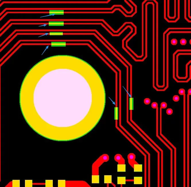
Why Do PCB Impedance-Controlled Traces Sometimes Require Local Solder Mask Openings?
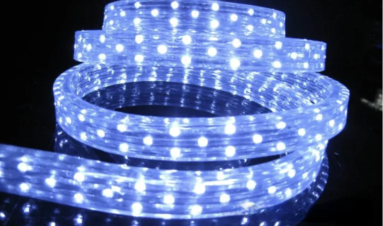
Why LEDs Emit Light but Ordinary Diodes Do Not
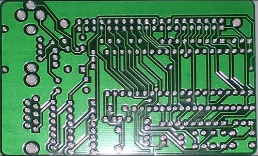
Why Does a PCB Designed for 50 Ω Measure 53 Ω After Manufacturing?
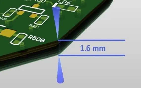
Why Does a 1.6 mm PCB Measure Only 1.4 mm? The Engineering Reality Behind PCB Thickness Calculations
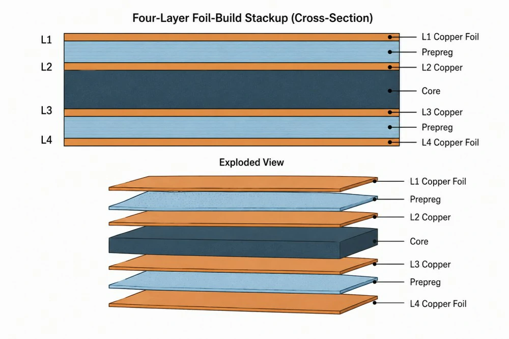
Multilayer PCB Construction Explained: Layers, Cores, Prepreg and Copper Foil
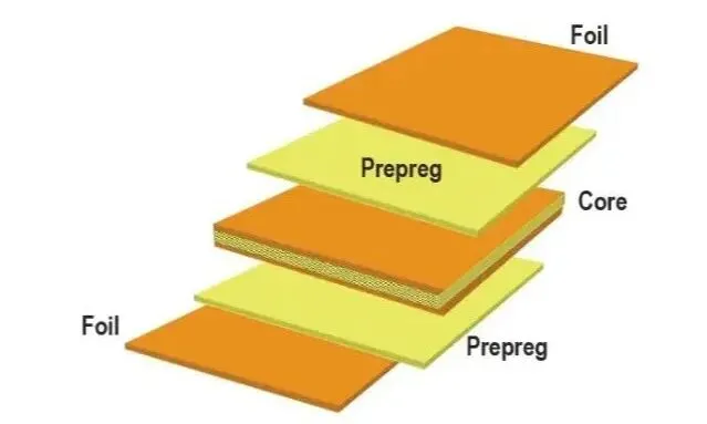
What Do 7628, 1080, and 2116 Mean in a PCB? Understanding These Numbers Means Understanding the Stack-Up
From Hardware to Chips: Exploring the Underlying Logic of Hardware Engineering
Time-Interleaved Sampling: A Key Technology in High-End Oscilloscopes

What Is an Eye Diagram and How to Read One?

Multilayer PCB Impedance Control: Design Rules for 4-Layer to 8-Layer PCBs

High-Speed Interface Routing on 6-Layer PCBs: DDR, USB and PCIe Design Considerations
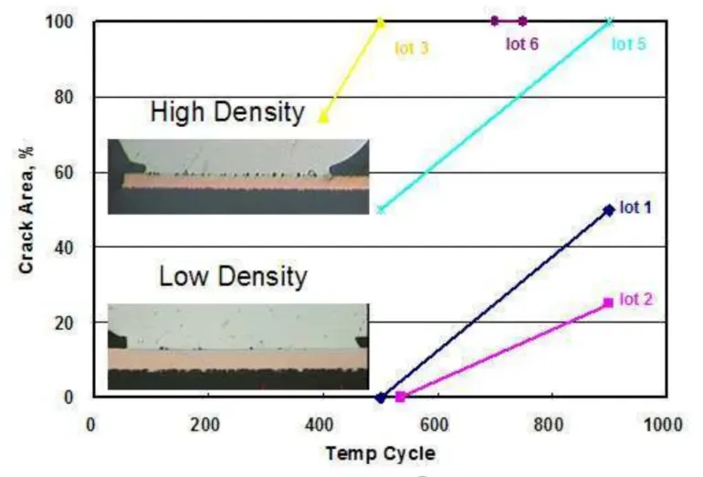
Key Differences Between Kirkendall Voids and Champagne Voids

What Is Cpk? Process Capability Index in Manufacturing
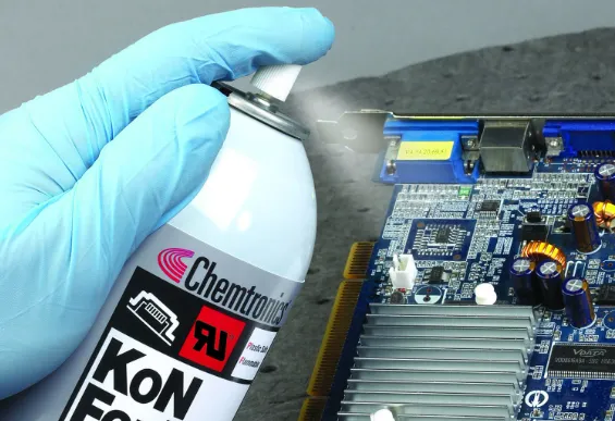
Conformal Coating for SMT Electronics: 50 Key Process Questions Answered
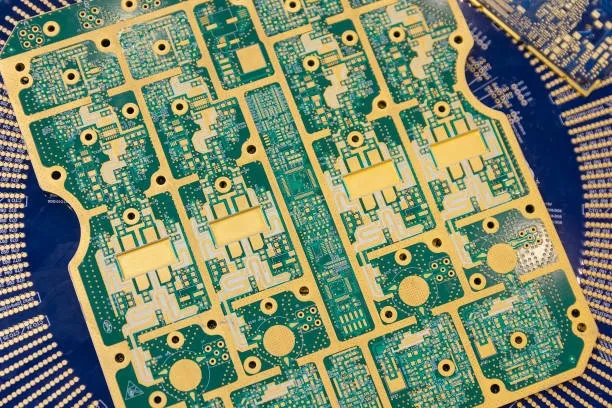
Troubleshooting Common Manufacturing Challenges with Rogers PCBs
Enhancing USB PCB Performance: A Guide to Optimal PCB Layout and Signal Integrity
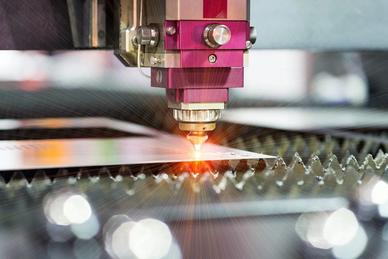
Optimizing Laser Drilling for Diverse PCB Materials: A Detailed Guide
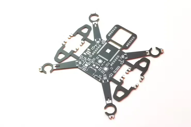
Designing High-Performance Drone Flight Controller PCBs: A Comprehensive Guide
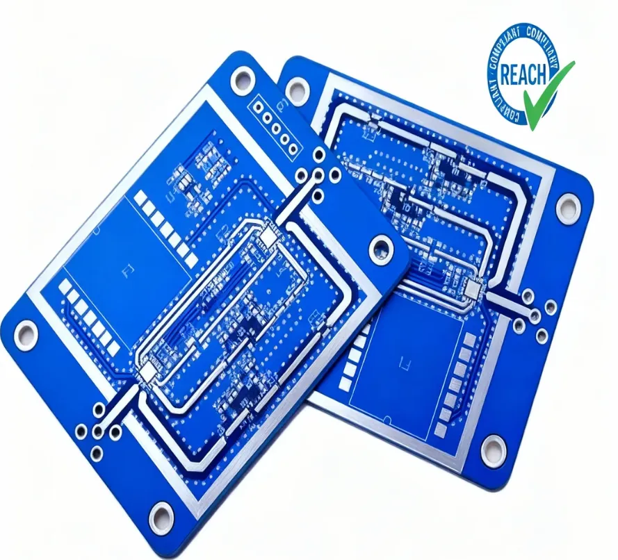
Navigating REACH for PCBs: A Guide for Electronics Engineers