02:50
PCB Vias
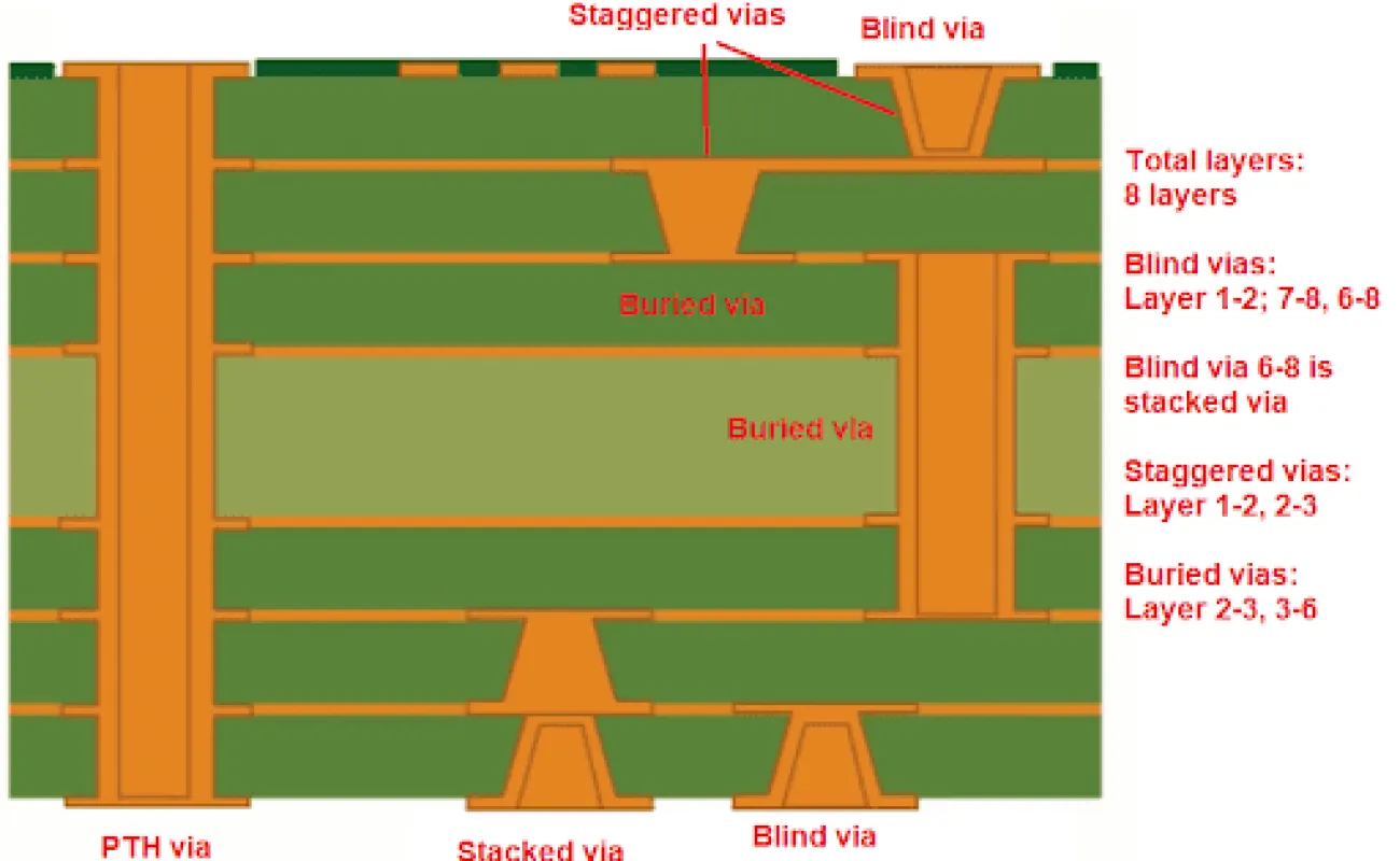
PCB vias are essential components in printed circuit board design, serving as conductive pathways that connect different layers of a multilayer PCB. These small plated holes enable electrical signals to travel vertically through the board, allowing for more compact and efficient layouts compared to single-layer designs. For engineers and hobbyists searching for information on PCB vias, this tag aggregates a wealth of resources that delve into their fundamental principles, helping you understand how they facilitate signal integrity, thermal management, and overall board performance in complex electronic systems. In practical terms, PCB vias come in various types, including through-hole vias that span the entire board, blind vias that connect an outer layer to an inner one without penetrating fully, and buried vias that link internal layers only. Each type offers specific advantages depending on your project's requirements, such as minimizing signal interference in high-speed circuits or optimizing space in densely populated boards. By exploring the articles under this tag, you can gain actionable insights into selecting the right via type for applications like RF designs, power electronics, or automotive systems, where reliability is paramount. Best practices for implementing PCB vias include adhering to design rules that prevent issues like via tenting, annular ring violations, or excessive thermal stress during soldering. For instance, ensuring proper via sizing and placement can reduce impedance mismatches and improve manufacturability, ultimately leading to fewer prototypes and faster time-to-market. Whether you're troubleshooting common problems like via voids or seeking tips on via stitching for ground planes, the content here provides detailed guidance grounded in industry standards. Diving into these articles will equip you with the knowledge to enhance your PCB designs, from basic concepts to advanced techniques, ensuring your projects meet both functional and production demands.
Video Guide
-
02:50
-
 00:54
Via Tenting vs Resin Plugging: When Do You Need Resin Filling for Via-in-Pad Designs?
-
 00:51
PCB Vias Plugging: Manufacturing Process, Failure Modes, and Reliability Impact
-
 00:57
PCB Solder Mask: Essential Protective Layer in Manufacturing
-
 00:54
PCB Vias: Critical Design Factors for Manufacturing Yield and Reliability
-
 00:57
PCB Antipad Design: 4 Key Factors for Reliable High-Speed Multilayer PCBs
-
 00:59
Via-in-Pad for BGA PCBs: When to Use It and Critical DFM Rules
-
 00:57
Tented vs Untented Vias — Why It Matters for Reliability
Technical Articles
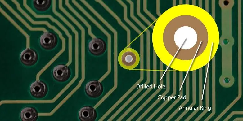
FR4 PCB Annular Ring: Design Rules and Reliability Considerations
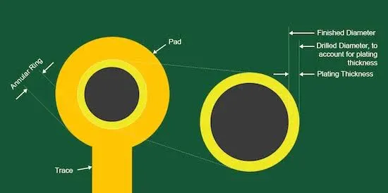
FR4 PCB Via Size and Pad Size: How to Choose the Right Dimensions
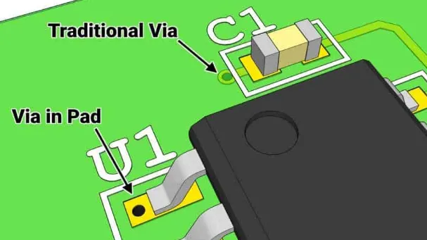
FR4 PCB Via-in-Pad: Benefits, Risks, and Design Considerations
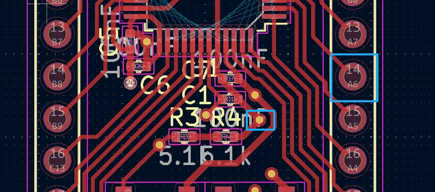
Via Design Guidelines for KiCad PCBs: Types, Rules and Manufacturing Considerations
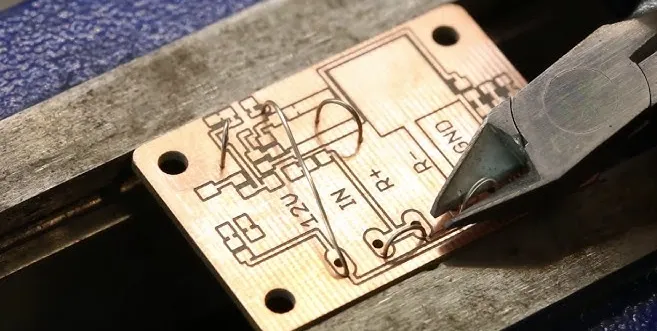
DIY PCB Vias: Creating Connections Between Layers at Home
Common Engineering Queries in 2 Layer FR4 PCB Design and Manufacturing
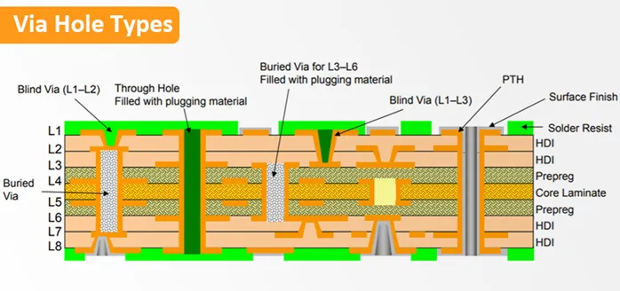
Mastering Blind and Buried Vias: How Sequential Lamination Enables Advanced Interconnects