


PCB Manufacturing
Printed Circuit Boards (PCBs) form the backbone of modern electronics, serving as the essential platform where components connect to create functional devices. In the PCB Manufacturing category, readers gain access to a comprehensive collection of resources designed to demystify the intricate processes involved in producing these critical elements. From initial design considerations to final assembly and testing, this category covers every stage, providing valuable insights for engineers, hobbyists, and industry professionals alike. Understanding PCB manufacturing is crucial for anyone involved in electronics development. This field encompasses a wide range of topics, including material selection, such as FR-4 substrates and advanced laminates, as well as fabrication techniques like etching, drilling, and soldering. Articles here delve into best practices for optimizing layouts to minimize signal interference, ensuring reliability in high-stakes applications. Tutorials guide users through prototyping methods, while in-depth analyses explore emerging trends like flexible PCBs and additive manufacturing, which are revolutionizing industries from consumer gadgets to aerospace systems. The practical value of mastering PCB manufacturing extends to real-world scenarios, where efficient production can reduce costs, enhance performance, and accelerate time-to-market. For instance, insights on multilayer board construction help in designing compact devices for IoT applications, and discussions on quality control standards prevent common pitfalls in mass production. By engaging with the diverse guides and expert perspectives in this category, readers can build a solid foundation in PCB technologies, apply proven strategies to their projects, and stay ahead in an ever-evolving field. Whether troubleshooting assembly issues or exploring sustainable manufacturing practices, the knowledge shared here empowers informed decision-making and innovation in electronics.
Latest Blogs
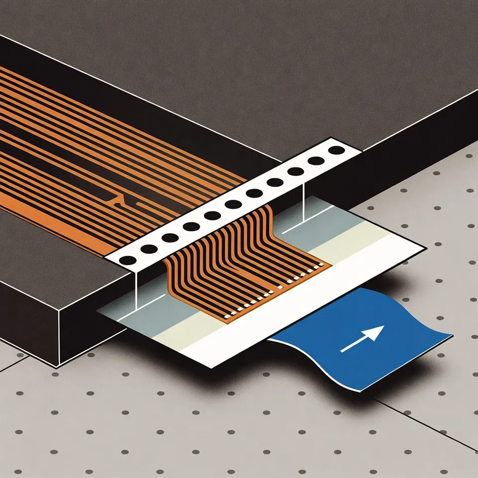
Best Way to Design Glue Paper Pull-out on FPC Panels
Discover factory-proven FPC glue paper pull tab design strategies for clean release liner removal. Learn how to optimize flex PCB adhesive handling for higher assembly efficiency, better yield, and smoother production from a real PCB fabrication perspective.
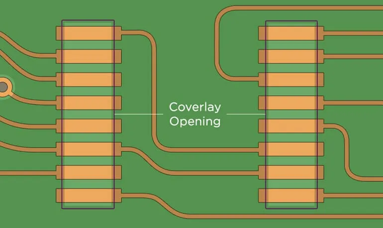
How Do FPC Factories Compensate Coverlay Openings in Practice?
Factory CAM view on FPC coverlay opening compensation practices. Learn single-side enlargement rules (0.05-0.15mm), stencil-matched adjustments, and how we handle differences from original design to ensure reliable SMT on flex PCB mask areas.
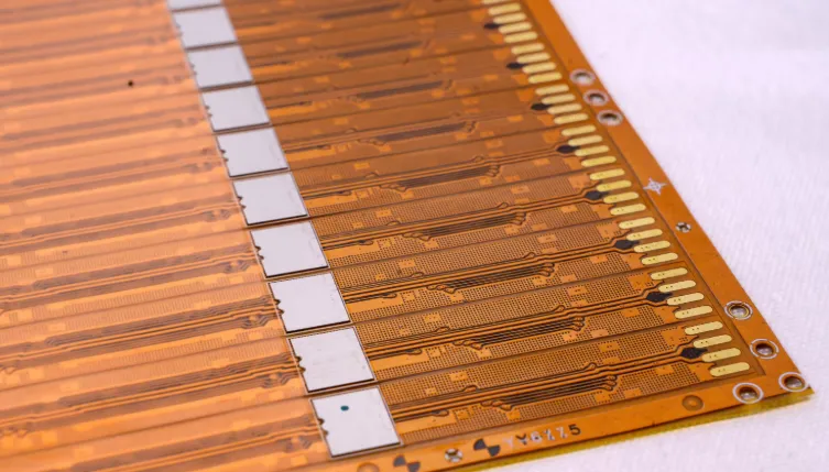
FR4 Stiffener Inner Shrink Rule for FPC Boards
From factory CAM perspective: standard FPC FR4 stiffener shrink rule for outlines and holes (0.15-0.3mm inner offset). Learn real production compensation methods, tolerance matching between lamination vs incoming material, and DFM recommendations to avoid misalignment and yield loss on flex PCB stiffener areas.
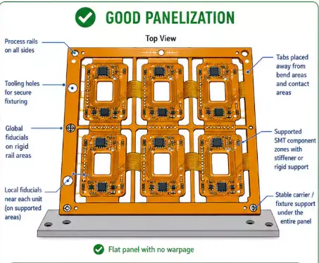
When Should You Add Waste Edge Protection on FPC Panels?
FPC waste edge design is essential for stable manufacturing and SMT handling. This guide covers recommended process edge sizes plus layout tips to prevent damage and improve flex PCB yield.
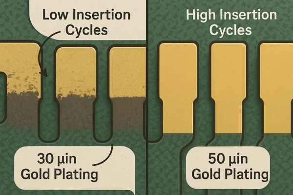
What Total Thickness Should You Control for FPC Insertion Finger Area?
Proper FPC finger thickness control ensures connector reliability. This guide covers FPC plus PI stiffener total thickness to achieve reliable insertion life cycles and higher assembly yield.
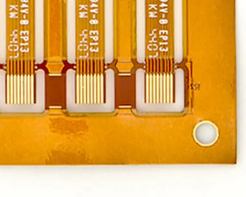
How Many Connection Points Are Needed for Stable FPC Panel Shipment?
Learn why FPC panel connection tabs are critical for manufacturing stability. We cover tab dimensions, placement rules, and DFM tips to prevent damage and ensure easy flex PCB depanelization.

HDI Manufacturing Process Flow: From Inner Layer to Any-Layer
Learn how HDI PCBs are manufactured from inner-layer preparation through sequential buildup, laser microvia drilling, via filling, plating, and final inspection, with key process controls for reliable HDI production.
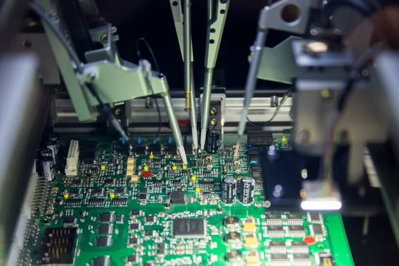
Challenges in using FPT
Challenges in using FPT stem from fine pitches and high pin counts, impacting solder paste application, placement accuracy, reflow defects, inspection, and component testing. Practical best practices and standards guide electric engineers to reliable PCB assemblies and higher yields.
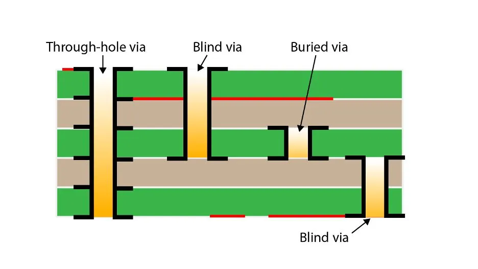
PCB Design Using Blind or Buried Vias Could Lower Fabrication Costs
Blind or buried vias in PCB design lower fabrication costs by reducing layer counts and optimizing routing under dense components like BGAs. This guide covers sequential lamination principles, cost-saving strategies, best practices, standards such as IPC-6012, and benefits to the assembly process for engineers.
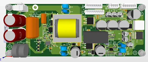
Thick Copper PCBs: Enabling Compact and Efficient DC DC Converters
Thick copper PCB for DC-DC converters supports high-efficiency power converter design in tight spaces. Explore planar transformer design, thermal management in DC-DC converters, and PCB layout for minimizing EMI with practical engineering tips and best practices for reliable performance.
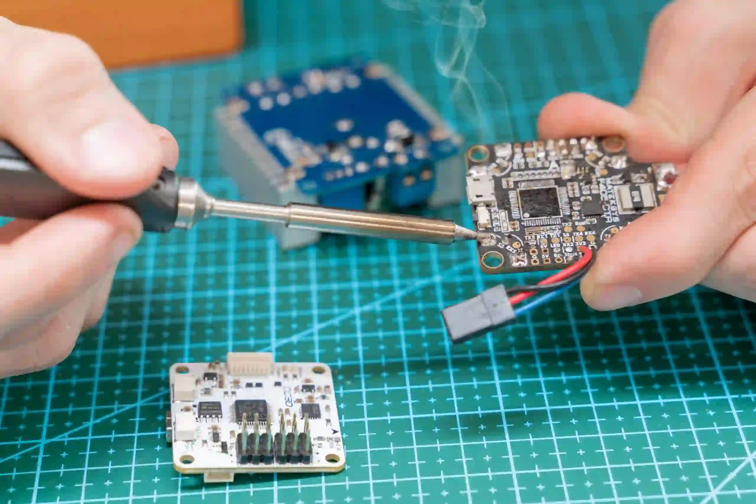
ICT in the Age of Miniaturization: Testing Micro Components on PCBs
ICT micro components testing on miniaturized PCBs faces SMT challenges from tiny pitches and dense layouts. This guide covers probe technology advances, best practices for alignment and fixtures, troubleshooting tips, and standards for reliable small component testing by electrical engineers.
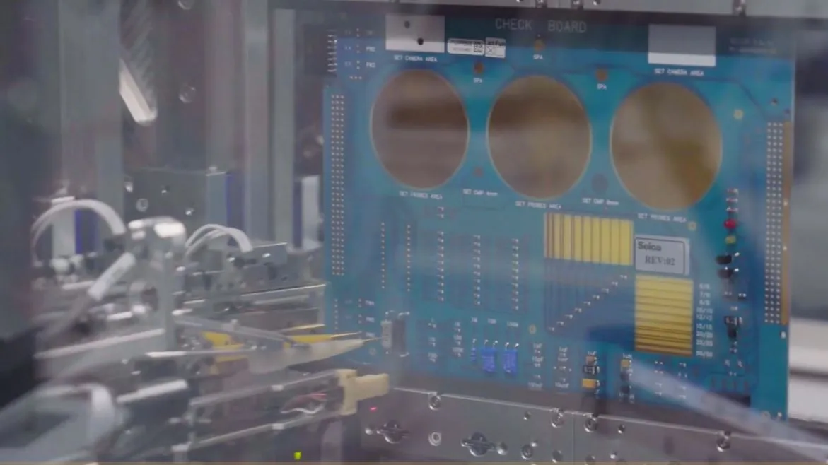
Avoid Costly Rework: Design for Testing (DFT) Strategies for IPC Compliant PCBs
Reduce costly rework on IPC compliant PCBs with Design for Testing (DFT) strategies. Learn PCB testing methods including flying probe testing, in-circuit testing (ICT), and automated optical inspection (AOI). Get practical best practices for electric engineers to boost test coverage, ensure compliance, and improve yields in production.


