 00:56
Copper Thickness
Copper thickness is a critical parameter in printed circuit board (PCB) design and manufacturing, referring to the weight of copper per unit area on the board's layers, typically measured in ounces per square foot (oz/ft²). Standard values range from 0.5 oz to 4 oz or more, directly influencing the board's electrical conductivity, thermal management, and mechanical strength. For engineers and electronics enthusiasts searching for information on copper thickness, this tag aggregates articles that delve into its implications for high-current applications, signal integrity, and overall PCB reliability. Understanding copper thickness helps in optimizing designs to prevent issues like overheating or voltage drops in power electronics. For instance, a 1 oz copper layer is common for low-power circuits, while thicker options like 2 oz or 3 oz are essential for high-amperage traces in automotive or industrial systems. Practical applications include calculating trace widths based on IPC standards to ensure safe current handling, selecting appropriate thicknesses for multilayer boards to minimize impedance mismatches, and evaluating trade-offs between cost and performance. Best practices involve consulting datasheets for components, using simulation tools to model thermal behavior, and considering fabrication constraints to avoid delamination or etching challenges. By exploring the resources under this copper thickness tag, users can gain actionable insights into real-world scenarios, such as upgrading from standard to heavy copper for LED drivers or troubleshooting failures in dense SMT assemblies. These articles provide detailed explanations, formulas for derating, and case studies that empower informed decision-making in PCB projects.
Video Guide


Technical Articles
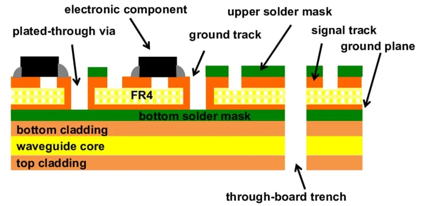
How to Calculate the Ideal Copper Foil Thickness for Your PCB Project
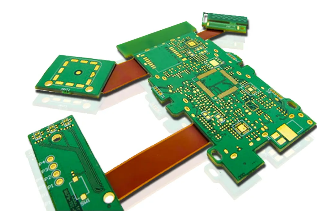
The Role of 1 oz Copper in Flexible PCBs: Benefits and Challenges
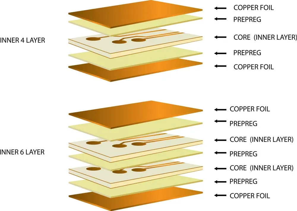
Understanding Copper Weight in PCB Stack Up: A Detailed Guide
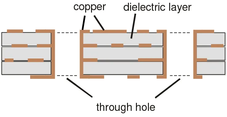
Copper Weight in PCB Manufacturing: Understanding Its Impact on Performance
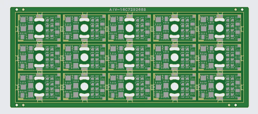
16 Layer PCB CAM Review: HDI Stackup Optimization and Resin Plugging for Reliable Fabrication
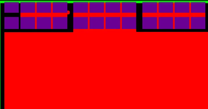
How PCB CAM Review Resolves Copper Weight and Panelization EQs on 8-Layer HDI Boards

4-Layer FR-4 TG170 PCB Case Study: Copper Overhang, Panelization & Legend Sizing Challenges During CAM Review
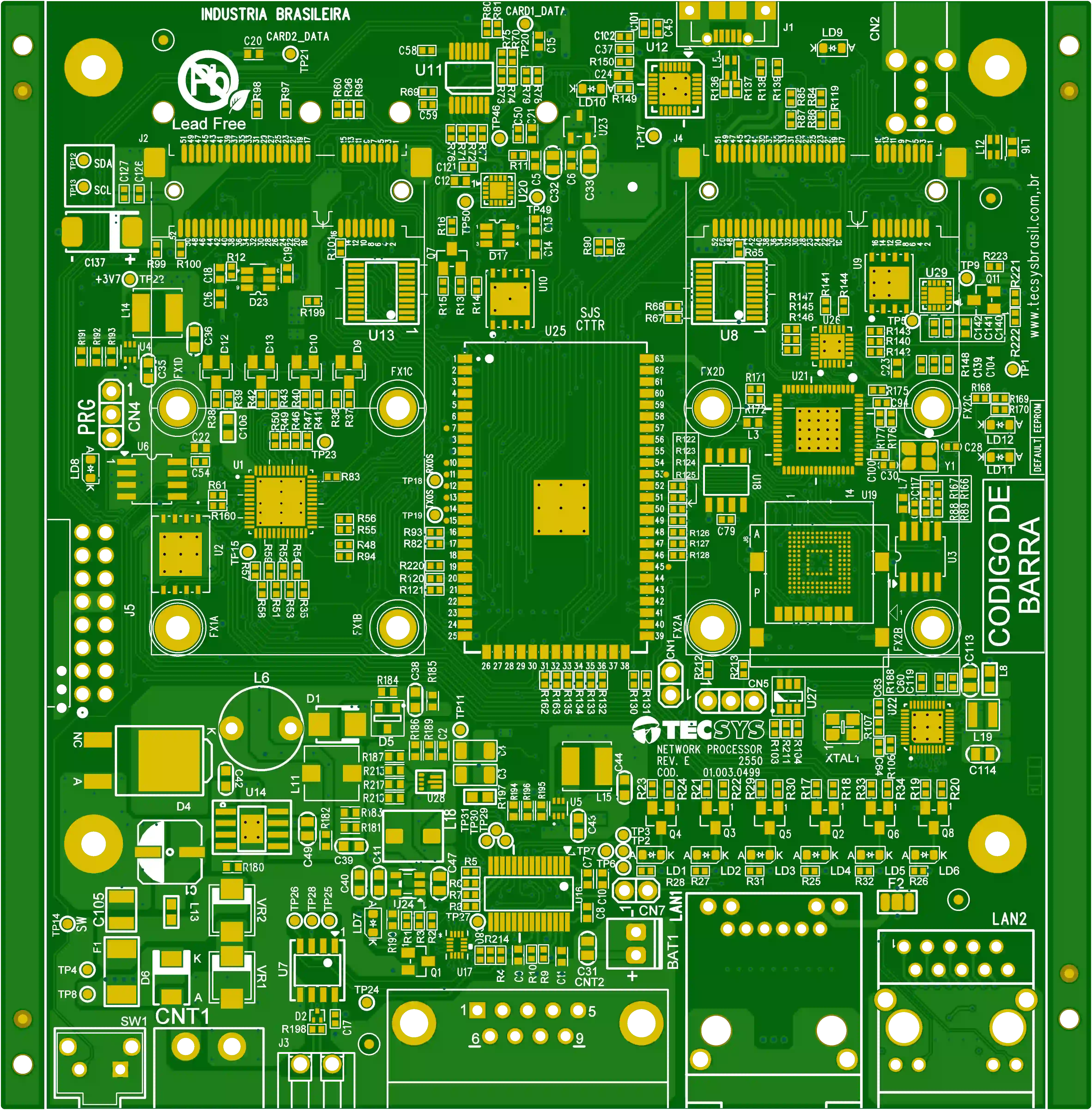
4-Layer PCB Design DFM: Resolving 3mil Fine Feature Conflicts

CNC Machining Cost Guide: What Factors Affect Pricing?
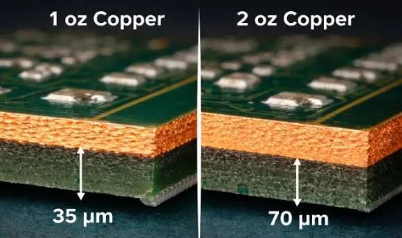
1oz vs 2oz Copper Thickness for HDI PCB: Which One Should You Choose?
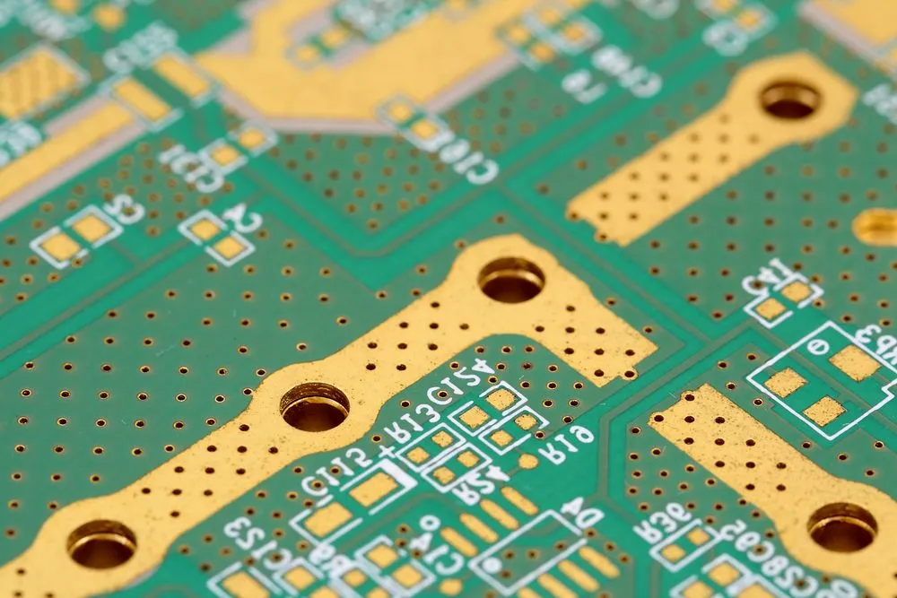
HDI PCB Design With Copper Thickness Options: CAM Review and Manufacturing Control
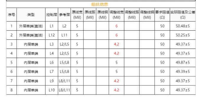
Resolving 12 layer FR4 PCB Copper Thickness and Impedance Conflicts
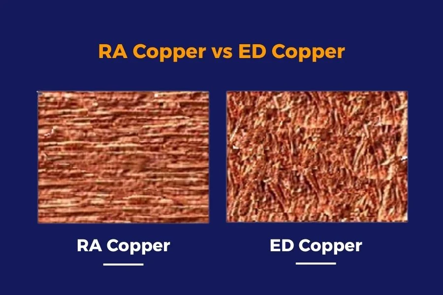
RA Copper vs ED Copper for Flexible PCB
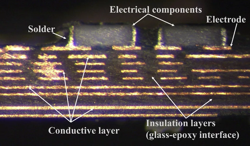
What Electrical Engineers need to know about Copper in Microns
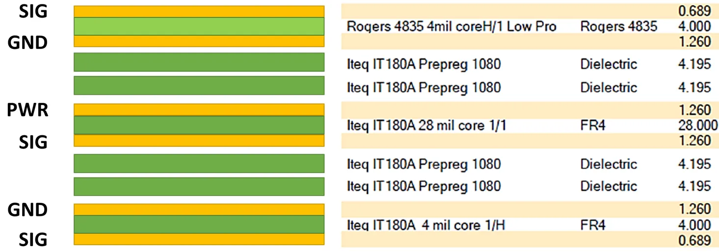
Exploring PCB Materials for Optimal Copper Thickness in RF Applications
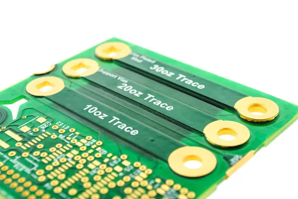
A Practical guide for hobbyist on Copper Thickness in PCB
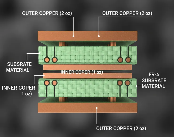
The Ultimate Guide to 2oz Copper PCB Design for Beginners
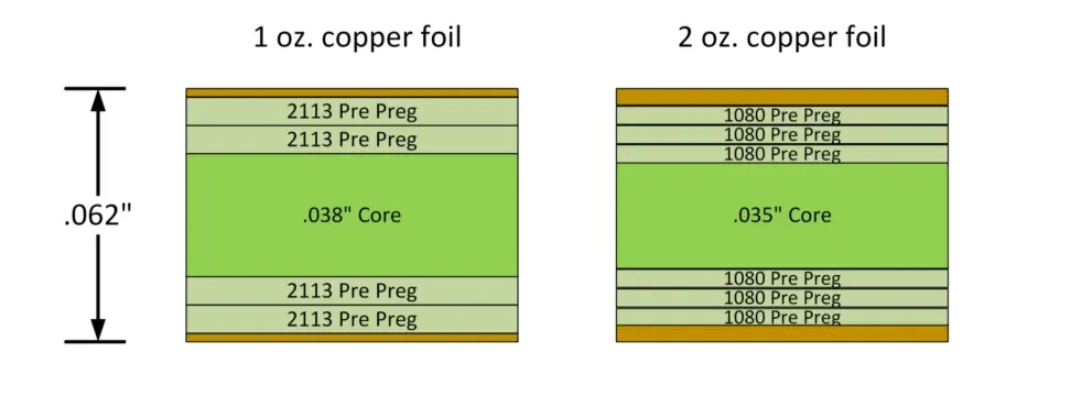
How to Choose Between 1oz and 2oz Copper PCBs For Your Project

Demystifying Copper Foil Thickness: A Beginner's Guide for PCB Hobbyists