 19:28
19:28
PCB Design Workflow
The PCB Design Workflow tag serves as a comprehensive resource for engineers, hobbyists, and professionals navigating the intricate process of printed circuit board development. At its core, this tag explores the end-to-end journey from initial concept and schematic capture to layout optimization, simulation, and final fabrication. Understanding a structured PCB design workflow is essential for minimizing errors, reducing time to market, and ensuring reliability in electronic products. Whether you are troubleshooting signal integrity issues or integrating advanced components like high-speed interfaces, the articles here provide practical guidance to streamline your projects. Key elements covered include best practices for tool selection, such as using software like Altium Designer or KiCad for efficient schematic-to-layout transitions, and strategies for iterative prototyping. For instance, implementing design rule checks early in the workflow can prevent costly revisions during manufacturing. Real-world applications range from consumer electronics to industrial automation, where optimized workflows enhance performance metrics like thermal management and electromagnetic compatibility. By following these insights, users can adopt modular approaches that facilitate collaboration in team environments and adapt to evolving standards like IPC-7351 for component footprints. For those seeking to refine their skills, the content delves into common challenges, such as managing multilayer boards or incorporating flexible PCBs, with step-by-step recommendations. Browsing through the tagged articles offers a wealth of knowledge to build robust designs, helping you achieve professional-grade results in your next project.
Video Guide

Technical Articles

The Nine Stages of Analog Circuit Design
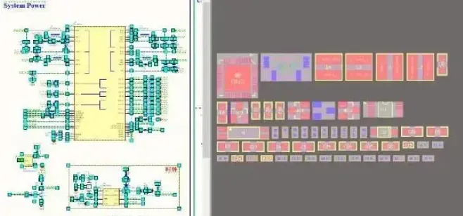
Boost PCB Design Efficiency with Interactive Cross-Probing and Modular Placement
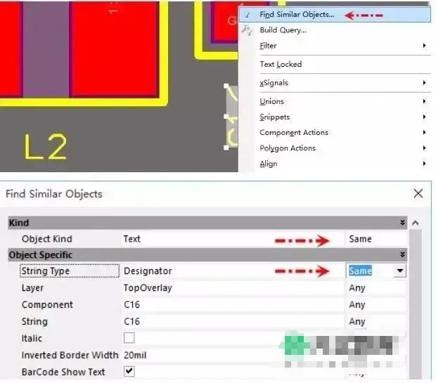
Global Editing Techniques in Altium Designer (Find Similar Objects)
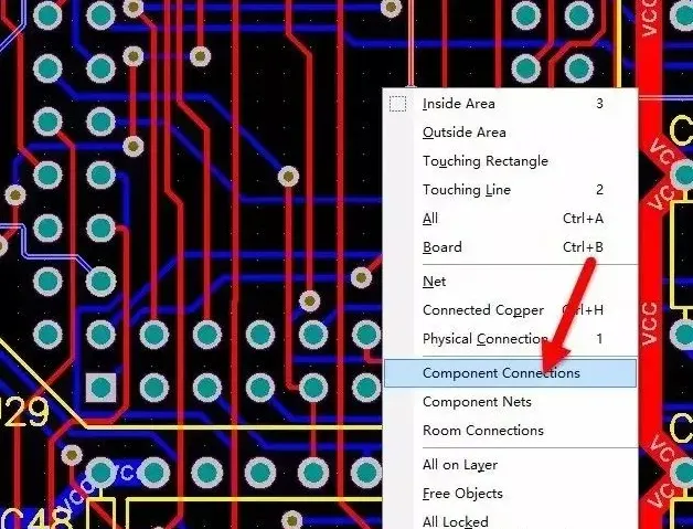
Selecting and Unrouting Nets Associated with a Component in PCB Layout
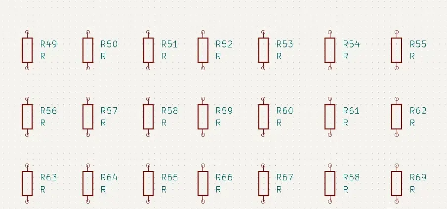
How to Continuously Place the Same Symbol in a KiCad Schematic

Precise Spacing Control: How to Move a Diagonal Feature by Exactly 1 mm
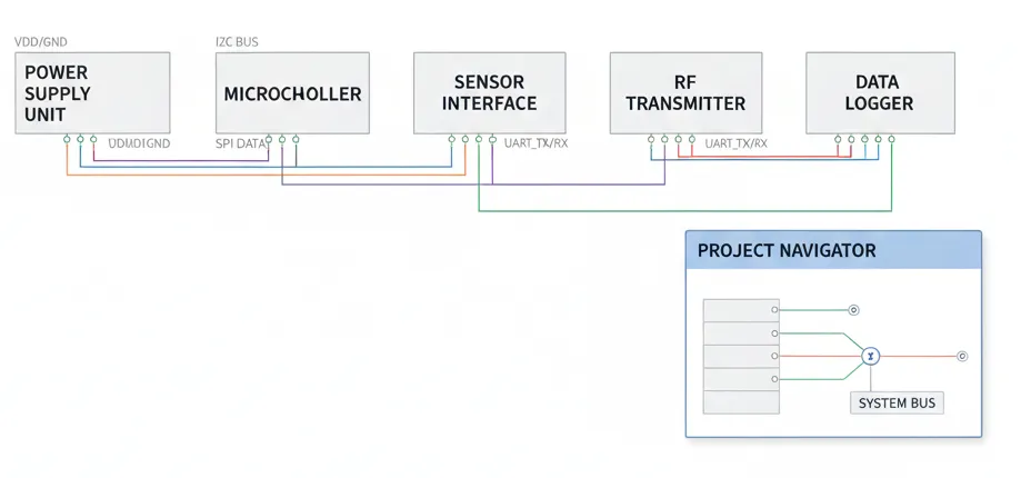
KiCad Finally Supports Flat (Tiled) Schematic Structure!
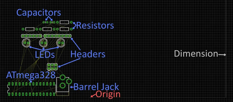
Stuck on PCB Placement? First Arrange These Four Types of Positions
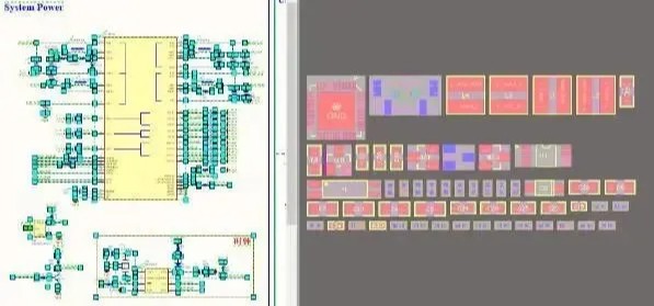
Interactive and Modular PCB Layouts to Double Design Efficiency
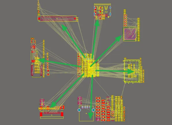
Standard PCB Design Workflow for Engineers

From Concept to Console: A Detailed Guide to Gaming PCB Layout

Converting Common Number Systems in PLCs
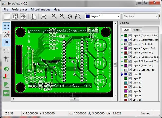
From Schematic to PCB: A Beginner's Guide to PCB Design Workflow
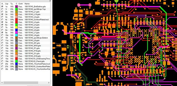
Gerber Files Unveiled: Understanding and Generating Gerber Files for PCB Manufacturing
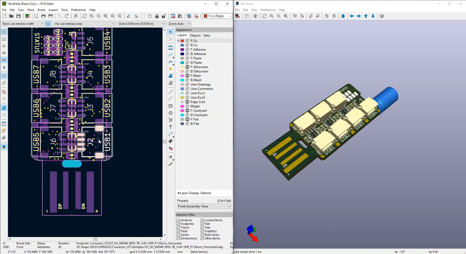
KiCad Ecosystem Explained: Tools, Libraries, Plugins, and PCB Manufacturing Resources

Five Stages of AI Model Development

Top 10 Common Machine Learning Algorithms
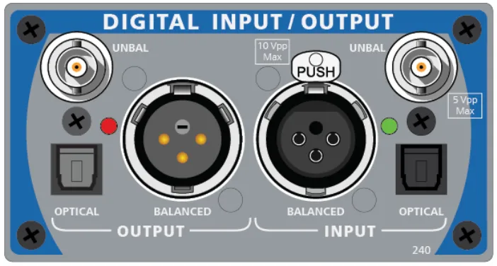
AP525 Test Platform Overview for Audio Measurements

Robot Hand-Eye Calibration Explained