Sequential Lamination
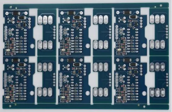
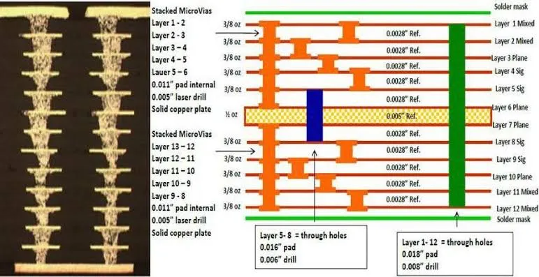
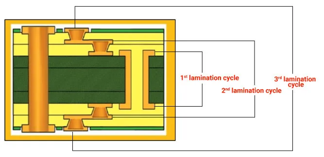
Sequential lamination is a sophisticated PCB manufacturing technique that involves building multilayer circuit boards by laminating subsets of layers in a stepwise manner, rather than pressing all layers at once. This method is particularly valuable for creating high-density interconnect (HDI) boards, where intricate via structures, such as microvias and buried vias, are essential for compact designs. By allowing precise control over layer alignment and bonding, sequential lamination minimizes issues like warping, delamination, and signal integrity problems that can plague traditional lamination processes. Engineers and designers searching for information on sequential lamination often seek ways to optimize board performance in applications like smartphones, automotive electronics, and medical devices, where space constraints and reliability are critical. One key advantage of sequential lamination lies in its ability to incorporate advanced features such as staggered vias and sequential build-up, which enhance electrical performance by reducing crosstalk and improving thermal management. For instance, in high-speed digital circuits, this technique enables finer pitch components and better impedance control, leading to more efficient signal transmission. Best practices include selecting compatible materials with matched coefficients of thermal expansion to prevent stress during multiple lamination cycles, and employing rigorous inspection methods like cross-sectional analysis to verify layer integrity. Designers should also consider the trade-offs, such as increased production time and cost, against the benefits of superior board density and functionality. For those looking to implement sequential lamination in their projects, understanding material selection and process parameters is crucial. Articles linked under this tag delve into case studies, design guidelines, and troubleshooting tips that can help refine your approach and avoid common pitfalls in PCB fabrication.
Technical Articles
Blind and Buried Vias in HDI PCBs: Design & Manufacturing Guide
High Density Interconnect (HDI) PCBs in Construction Equipment: Is It Worth It?
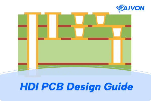
HDI Design Guide: Stackup Principles, Microvia Reliability and High-Density Routing Guide
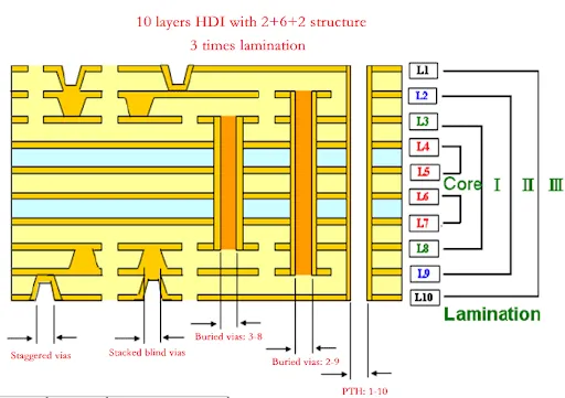
Via Aspect Ratio in PCB Design: Considerations for HDI Complex PCBs
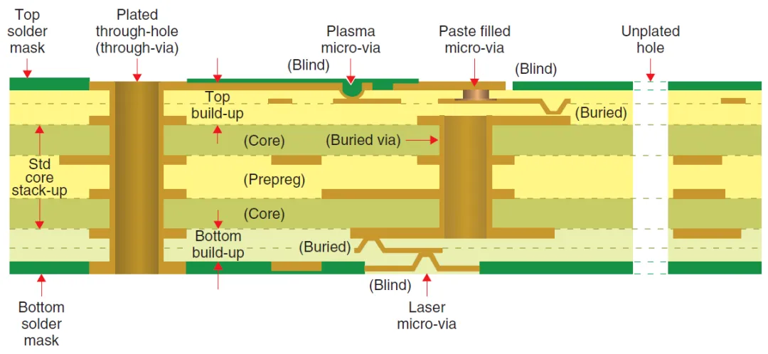
Microvia Aspect Ratio: Achieving High Density Interconnects
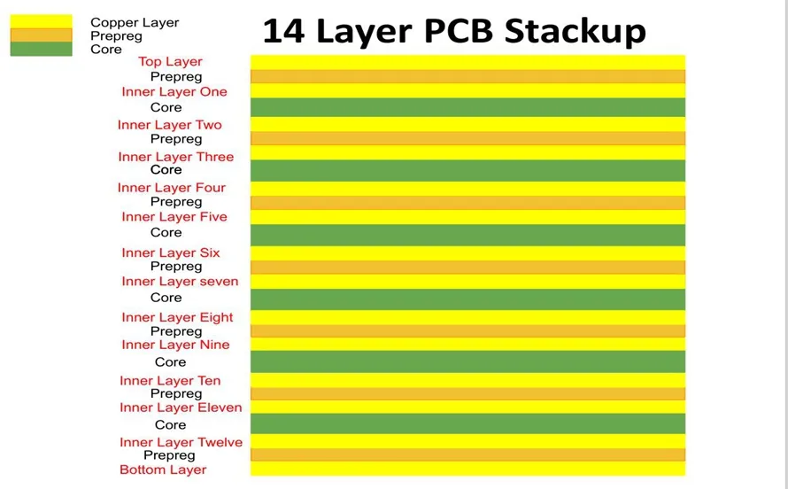
Sequential Lamination for RF and Microwave PCBs: Optimizing Performance in High Frequency Applications
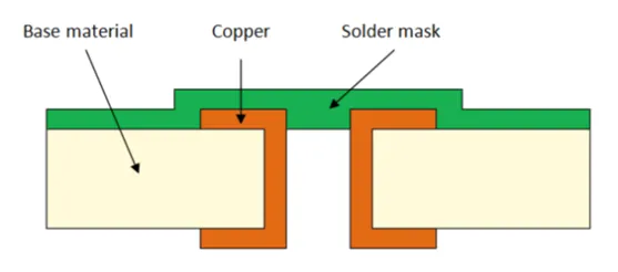
PCB via Plating: A Comprehensive Guide
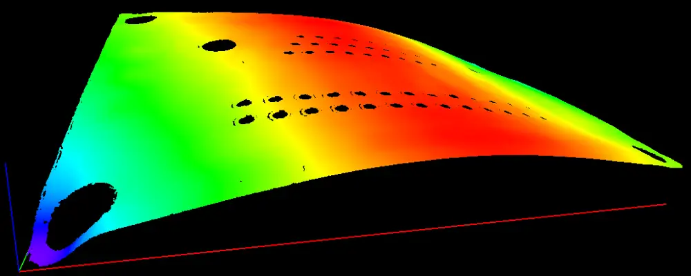
The Impact of Copper Weight on Sequential Lamination in High Power PCBs
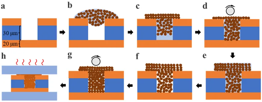
Sequential Lamination and Via in Pad: Maximizing Component Density on HDI PCBs
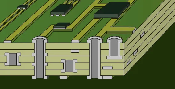
Blind Via Design Rules
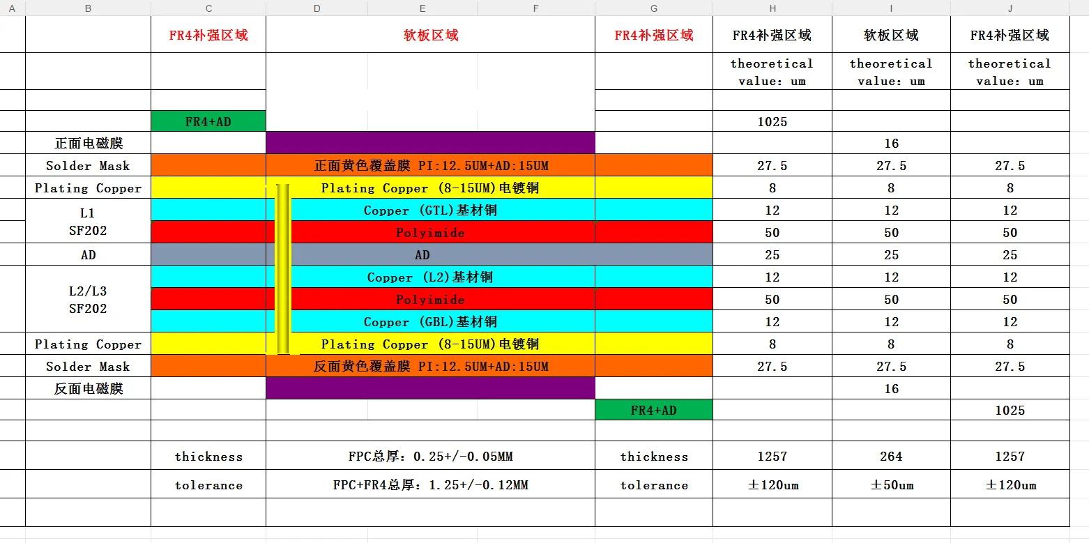
PCB Stackup, Impedance and Thickness Issues in CAM Review
Standard FR4 vs High-Tg FR4: Which PCB Material Should You Choose?
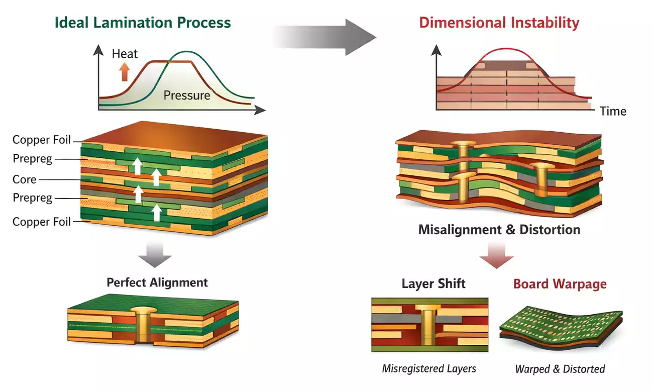
FR4 PCB Registration Accuracy: Causes of Layer Misalignment
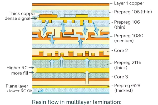
FR4 PCB Resin Flow: Effects on Multilayer Manufacturing
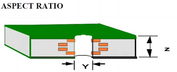
FR4 PCB Hole Aspect Ratio: Why It Matters for Plating Reliability
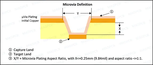
HDI Microvia Pad Size: How Much Annular Ring Is Enough?
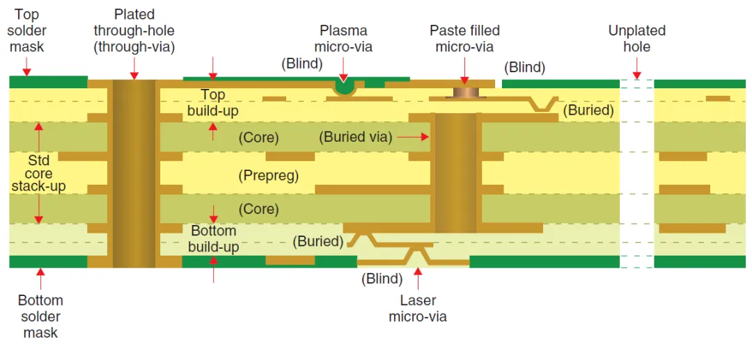
HDI PCB Registration Tolerance: What Designers Should Check Before Release
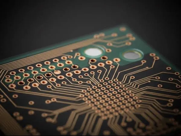
HDI PCB Design Changes After CAM Review: What Usually Goes Wrong?