High-Speed PCB
High-speed printed circuit boards (PCBs) are essential components in modern electronics, enabling the reliable transmission of signals at frequencies exceeding 100 MHz. These specialized boards address the challenges of signal integrity, electromagnetic interference, and thermal management in applications such as telecommunications, data centers, automotive systems, and high-performance computing. For engineers and designers searching for High-Speed PCB resources, this tag serves as a comprehensive hub, offering in-depth guidance on optimizing designs to prevent issues like crosstalk, reflections, and timing errors that can degrade performance. Understanding the fundamentals of high-speed PCB design begins with selecting appropriate materials, such as low-loss dielectrics and controlled-impedance traces, to maintain signal quality over long distances. Best practices include implementing proper layer stacking for multilayer boards, using differential signaling to reduce noise, and incorporating ground planes to minimize EMI. Practical applications often involve simulation tools like SPICE or electromagnetic field solvers to predict and mitigate potential problems before prototyping, saving time and costs in the development cycle. For instance, in 5G infrastructure, high-speed PCBs ensure seamless data transfer rates, while in consumer electronics, they support faster processing in devices like smartphones and gaming consoles. Professionals tackling high-speed projects can benefit from actionable insights on via optimization, such as back-drilling to eliminate stubs, and routing techniques that prioritize signal path length matching. This collection of articles explores these topics through real-world examples and case studies, helping you apply proven strategies to your own designs. Whether you are refining an existing layout or starting a new high-frequency project, the resources here provide the technical depth needed to achieve robust, efficient results.
Technical Articles

Stop Drawing Arbitrary Serpentine Traces: The Real Constraint in PCB Length Matching
High-Speed PCB Design: From Signal Integrity to Transmission-Line Basics
After Designing 10 PCBs: If the Layers Are Wrong, the Board Is Wasted
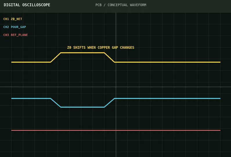
Why Impedance Changes After Adjacent Copper Pour Even When Trace Width Does Not
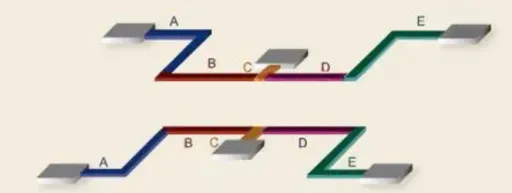
PCB Design Keep Going Wrong? 13 Key Fundamentals That Build a Solid Baseline
Can a 0 Ω Resistor Really Be Used as a Jumper? A Trap Many Engineers Have Hit
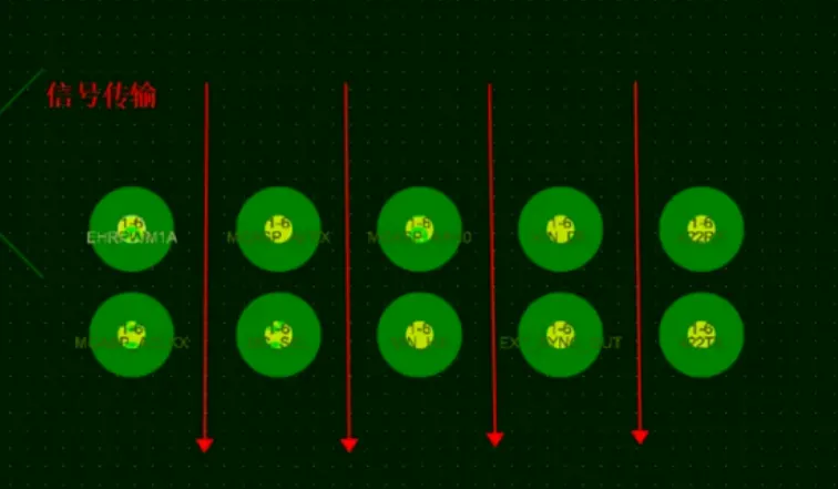
High-Speed PCB Vias: A Small Feature That Can Break the Signal
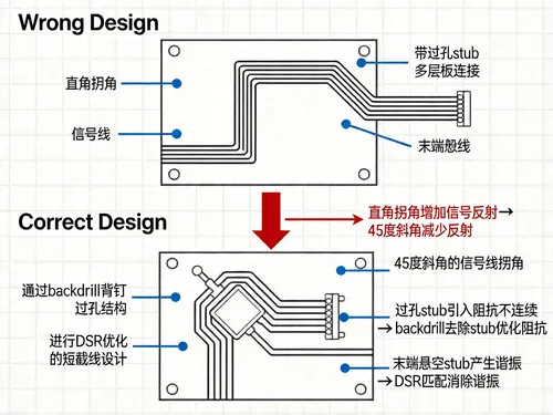
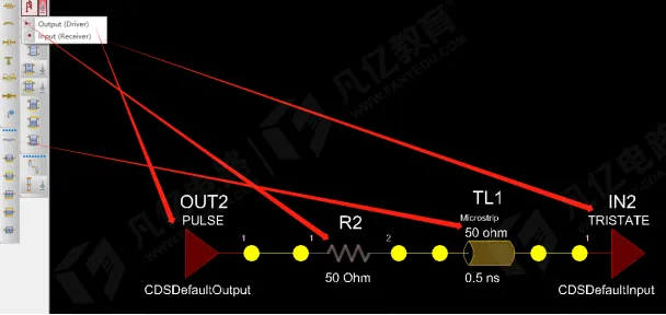
Signal-Integrity Simulation: Five Places Designs Usually Break
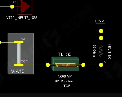
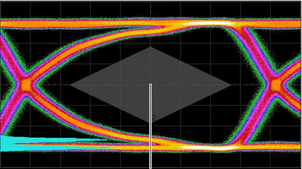
Unstable DDR Is Not Always a Chip Problem: How Much Does a 39 Ω Termination Resistor Change the Eye Diagram?
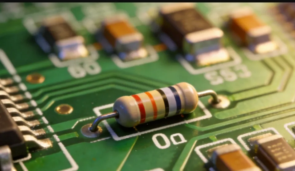
Is a 0 Ω Resistor Only a Jumper? Six Practical Uses in Hardware Design
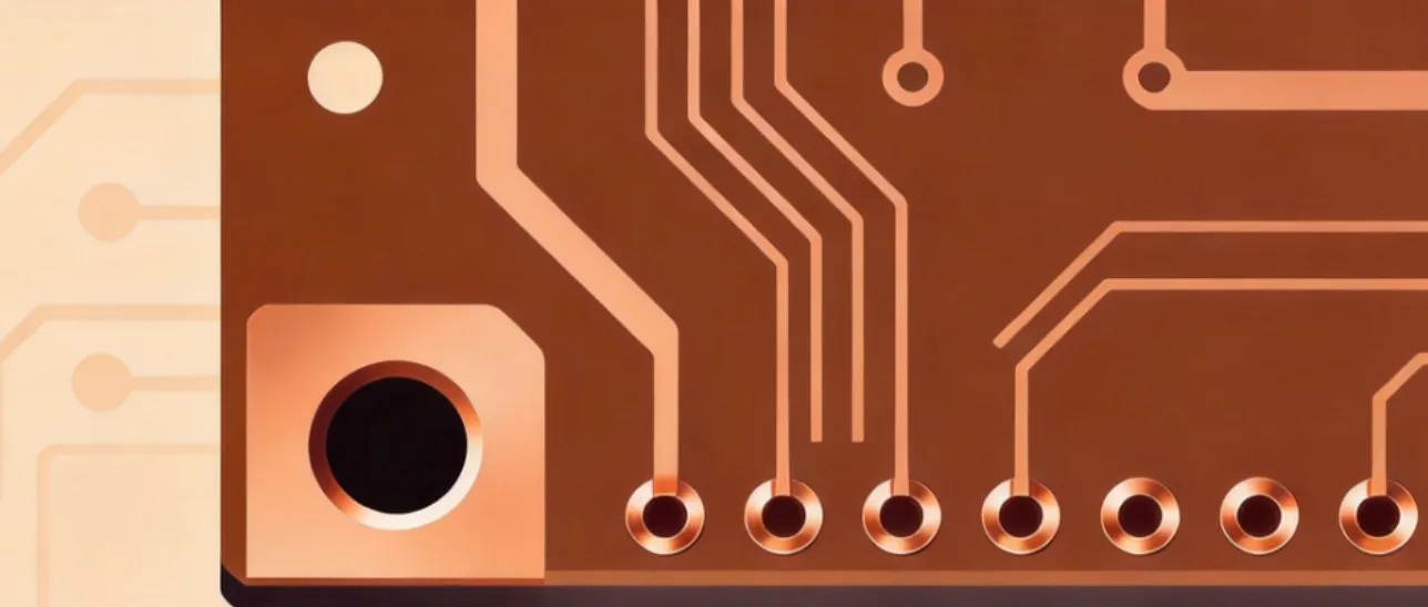
How to Reduce Via Parasitic Inductance in High-Speed Routing
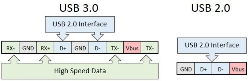
A USB Port Looks Simple. A Bad PCB Layout Turns It Into a Signal Problem

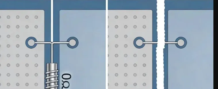
Why Backdrill Stubs Can Still Be Too Long After the Layer Pair Is Correct
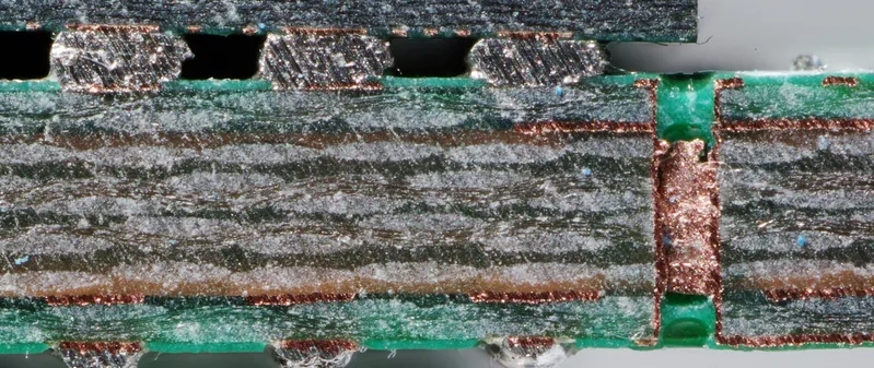
Small Anti-Pads Can Cause Unconnected Vias to Short
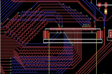
FR4 PCB Differential Pair Routing: Spacing and Length Matching
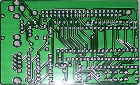
Why Does a PCB Designed for 50 Ω Measure 53 Ω After Manufacturing?
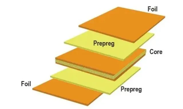
What Do 7628, 1080, and 2116 Mean in a PCB? Understanding These Numbers Means Understanding the Stack-Up
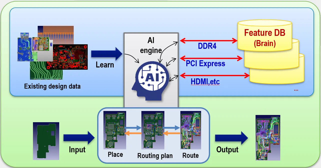
How AI Can Assist Multilayer PCB Routing and Design