 00:52
00:52
Flexible PCB
Flexible PCBs, also known as flex circuits, represent a versatile advancement in printed circuit board technology, allowing for designs that bend, fold, and conform to irregular shapes without compromising electrical performance. These boards are constructed from flexible substrates like polyimide or polyester, enabling their use in compact, space-constrained applications where rigid PCBs would be impractical. For engineers, designers, and hobbyists searching for information on Flexible PCB, this tag serves as a comprehensive resource covering essential topics such as material selection, manufacturing processes, and integration strategies that ensure reliability in dynamic environments. One of the primary advantages of Flexible PCBs is their ability to reduce weight and improve durability in products like wearable devices, medical implants, automotive sensors, and aerospace components. By eliminating the need for bulky connectors and wiring harnesses, they streamline assembly and minimize failure points, which is crucial for high-vibration or high-movement scenarios. When designing with Flexible PCBs, best practices include optimizing trace routing to avoid stress concentrations, selecting appropriate adhesives for layer bonding, and conducting thorough bend testing to predict lifespan. Understanding these elements can help prevent common issues like delamination or signal integrity loss, ultimately leading to more efficient prototypes and production runs. This tag aggregates articles that delve into real-world case studies, such as implementing Flexible PCBs in consumer electronics or troubleshooting fabrication challenges. Readers interested in advancing their projects can find guidance on cost-effective prototyping methods, compliance with standards like IPC-6013, and comparisons with rigid-flex hybrids. Whether you are exploring initial concepts or refining advanced designs, the content here provides practical insights to enhance your electronics innovations.
Video Guide
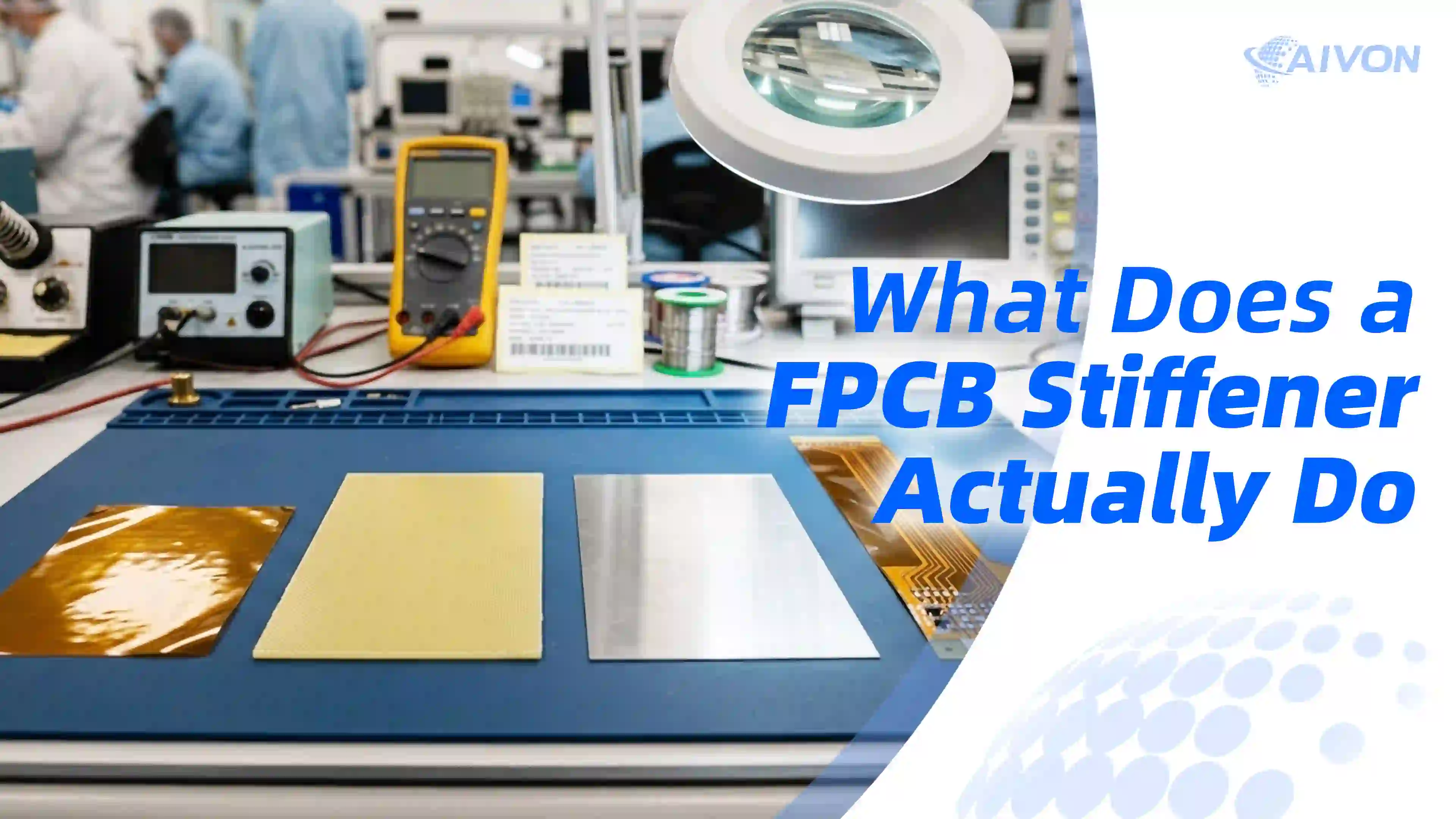
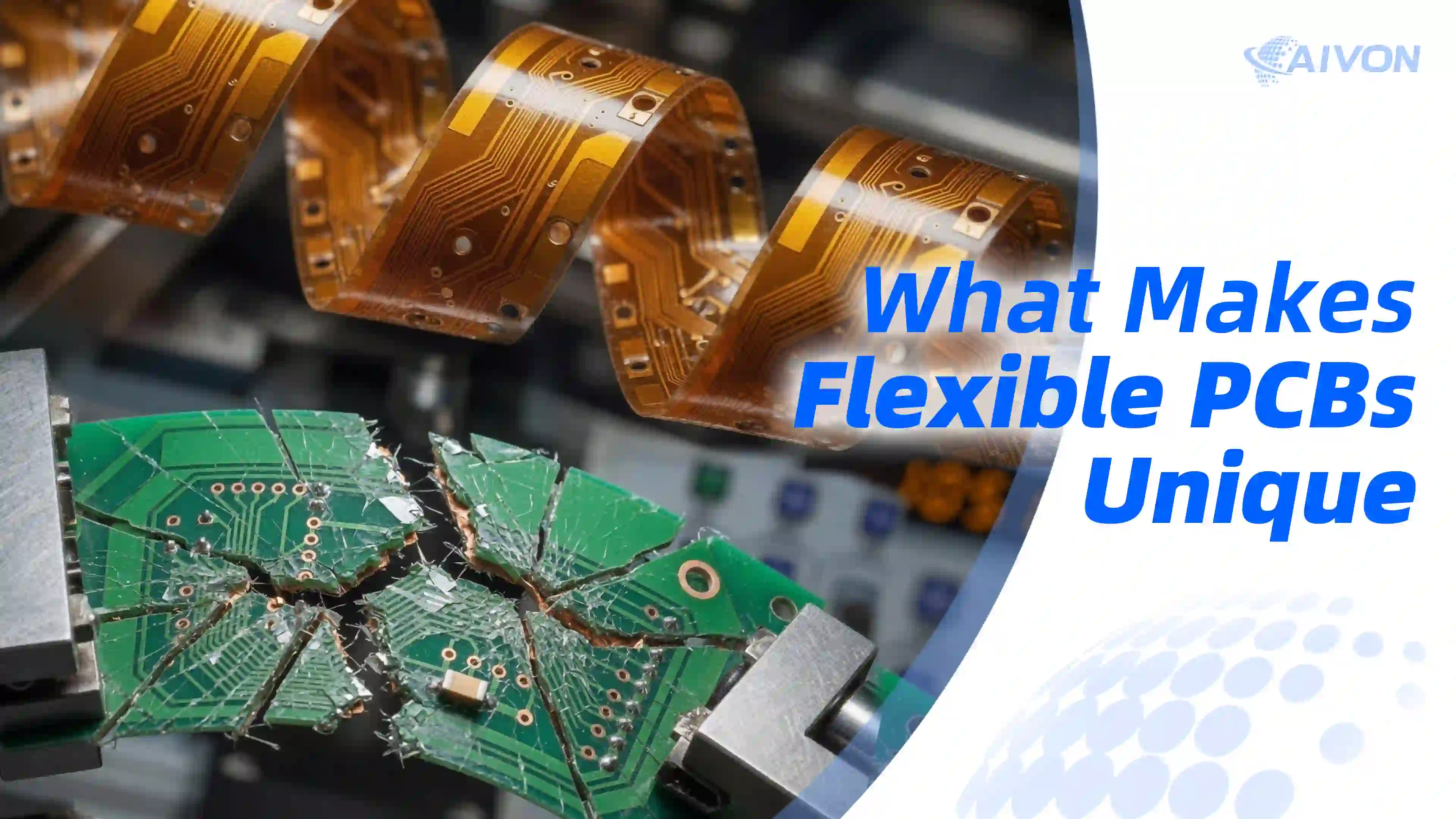

Technical Articles

Sustainable Flexible Circuits: The Rise of Bio-Based Flexible PCBs
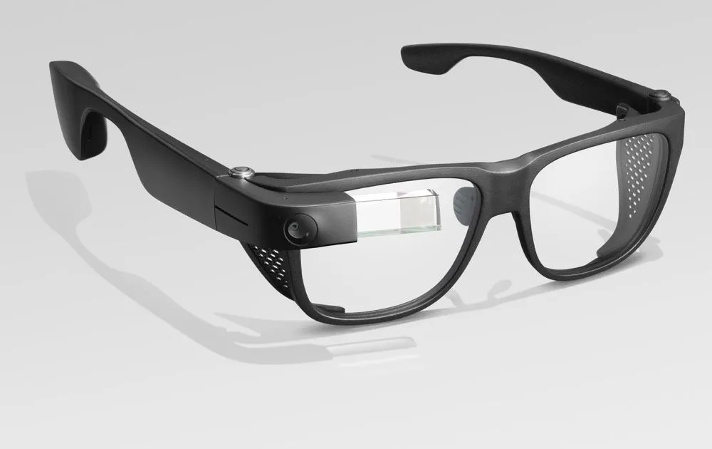
Flexible PCBs for Smart Eyewear: Design, Materials, and Assembly

Flexible PCB for Medical Wearable Devices: Design & Applications
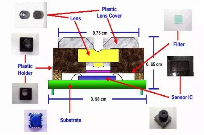
Mobile Camera Structure and Imaging Principles
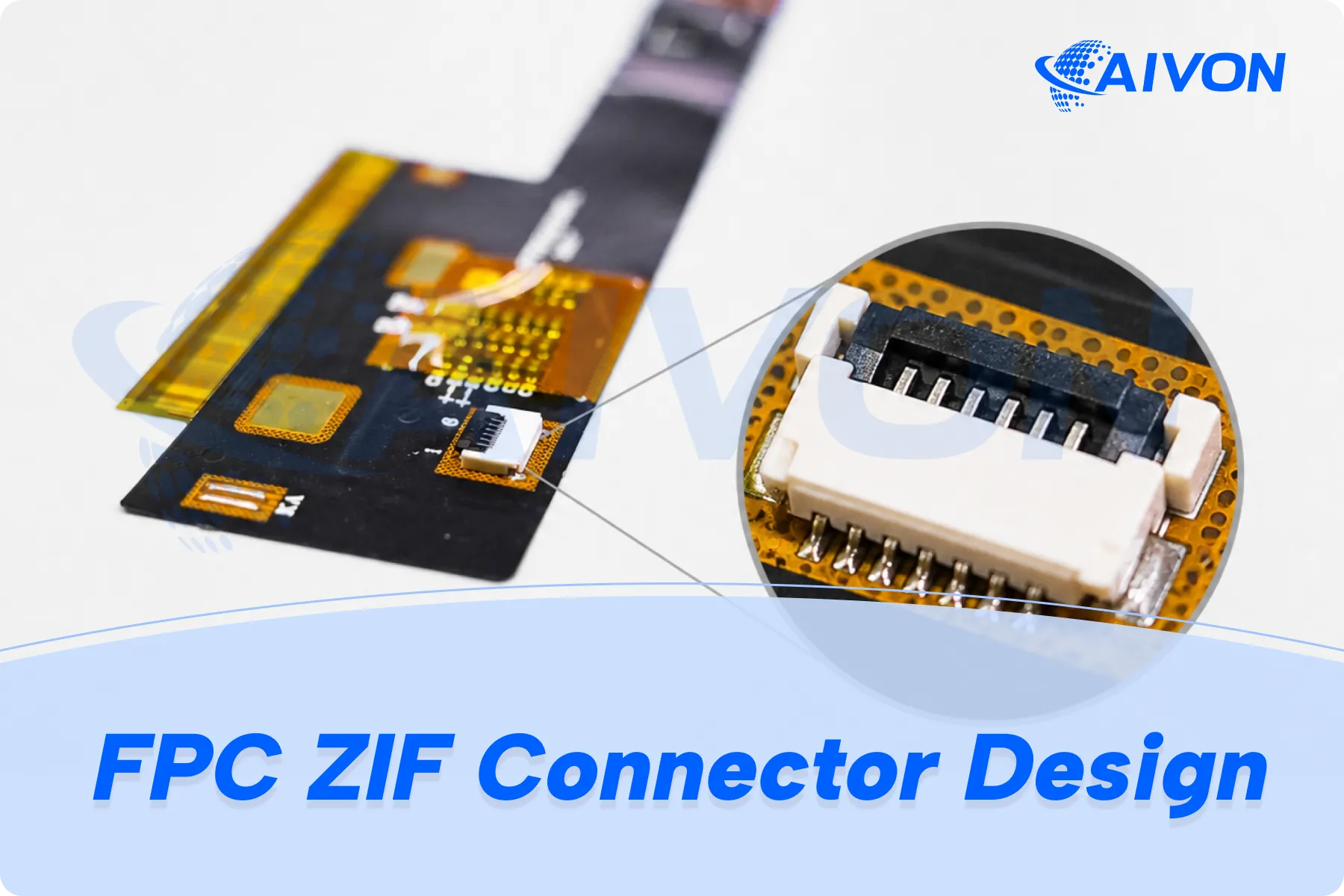
FPC Connector and ZIF Interface Design Best Practices
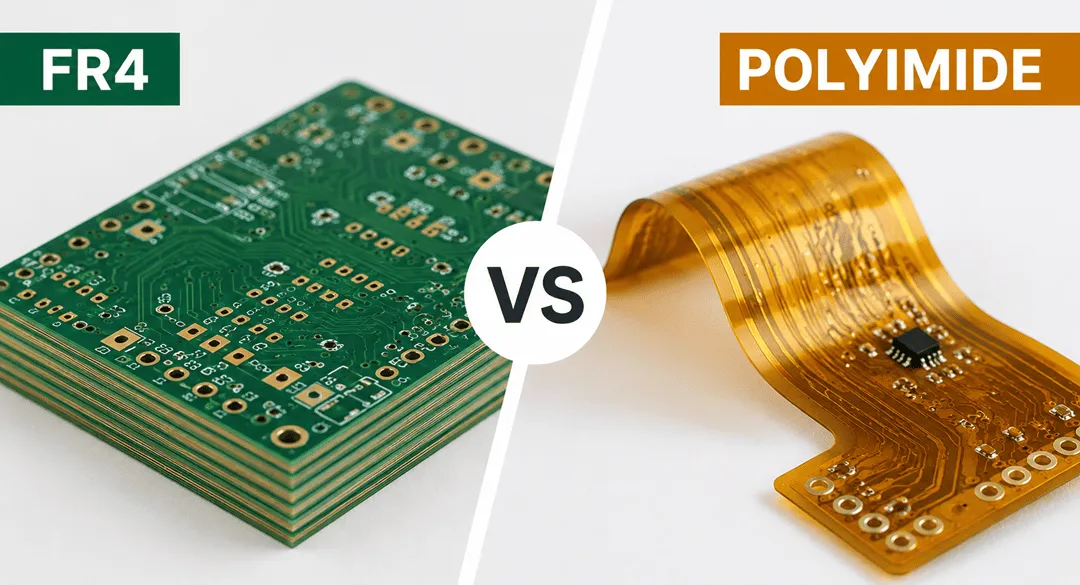
FR4 vs Polyimide PCB: Which Material Is Better for Your Application?

Flex PCB Bend Radius: FPC Bending Rules and Design Guide

Static vs Dynamic FPC: Design Rules, Bend Radius, and Material Selection
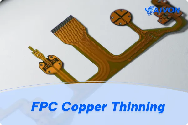
FPC Copper Thinning: FPC Thickness Selection, Techniques and Design Guidelines
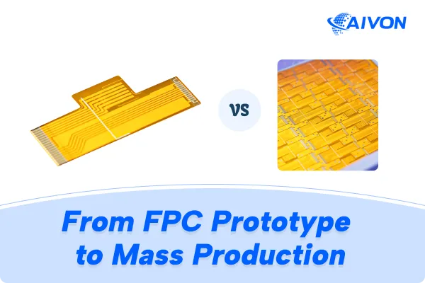
From FPC Prototype to Mass Production: Manufacturing Considerations

Dimensional Stability in FPC Manufacturing: Causes and Solutions

Can 0.1mm PI Stiffener Achieve 0.3mm FPC Total Thickness?
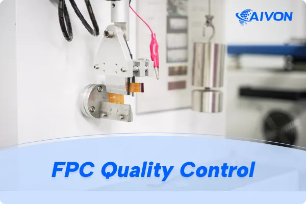
Quality Control in FPC Manufacturing: Key Inspection Points
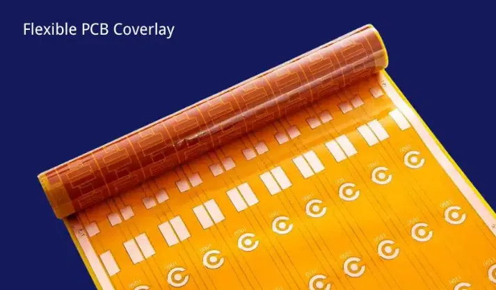
What Happens If FPC Coverlay Opening Is Too Large?
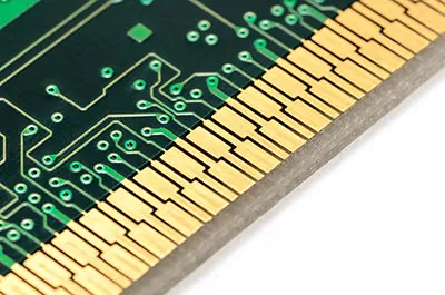
Hard Gold Plating Thickness for FPC Gold Fingers

Why Does FPC Coverlay Lift or Peel During Use?
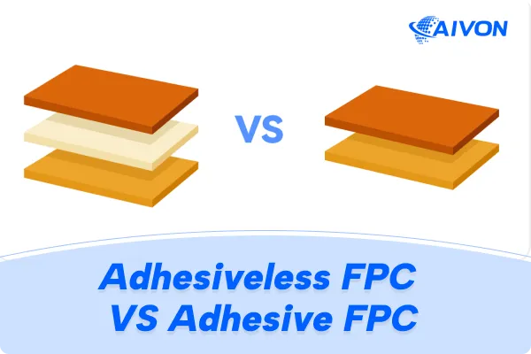
Adhesiveless vs Adhesive FPC: Which One Should You Choose?

Common FPC Manufacturing Defects and How to Prevent Them
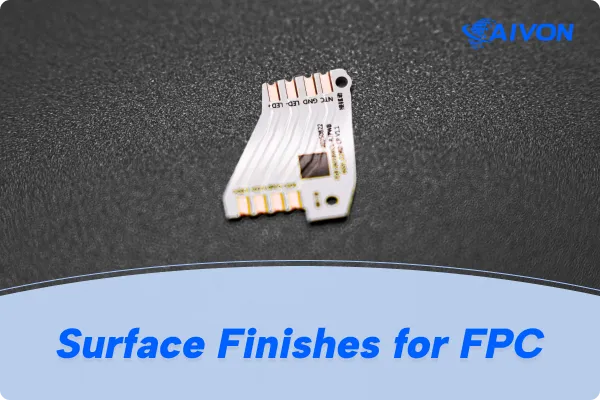
FPC Surface Finish: Types, Selection, and Design Considerations