


PCB Design
Printed Circuit Board (PCB) design forms the backbone of modern electronics, enabling the creation of compact, efficient, and reliable devices that power everything from smartphones to industrial machinery. In this category, readers gain access to a comprehensive collection of resources dedicated to mastering PCB design principles and techniques. Whether you are a seasoned engineer refining complex layouts or a newcomer learning the fundamentals, these articles provide the knowledge needed to tackle real-world challenges in electronics development. The scope of PCB design covered here extends from initial schematic capture to final board fabrication and testing. Articles delve into essential topics such as layer stacking, signal integrity, thermal management, and component placement strategies. Guides and tutorials offer step-by-step instructions for using popular software tools like Altium Designer and KiCad, while insights explore emerging trends like flexible PCBs and high-speed designs. Best practices emphasize error reduction, cost optimization, and compliance with industry standards, ensuring designs are not only functional but also manufacturable at scale. Real-world applications highlight the category's practical value, demonstrating how effective PCB design contributes to innovations in automotive systems, medical equipment, renewable energy solutions, and consumer gadgets. By addressing common pitfalls and sharing expert tips, these pieces equip professionals to enhance product performance and reliability. Readers benefit from building a deeper understanding through interconnected articles that cover foundational concepts alongside advanced methodologies, fostering continuous improvement in electronics projects. For those involved in prototyping or production, the technical relevance of this content lies in its focus on efficiency and innovation. Detailed discussions on impedance control, EMI shielding, and design for manufacturability prepare you to meet the demands of today's fast-paced tech landscape. Engaging with multiple articles in this category allows for a progressive learning path, where foundational knowledge supports exploration of specialized topics, ultimately leading to more robust and innovative PCB designs.
Featured Blog
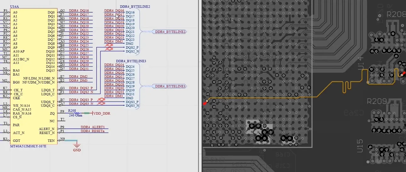
PCB Design Review for Beginners: A Step by Step Guide
Learn how to perform a PCB design review with a practical checklist covering schematics, layout, DRC, manufacturability, and pre-production checks.
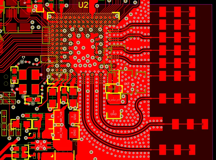
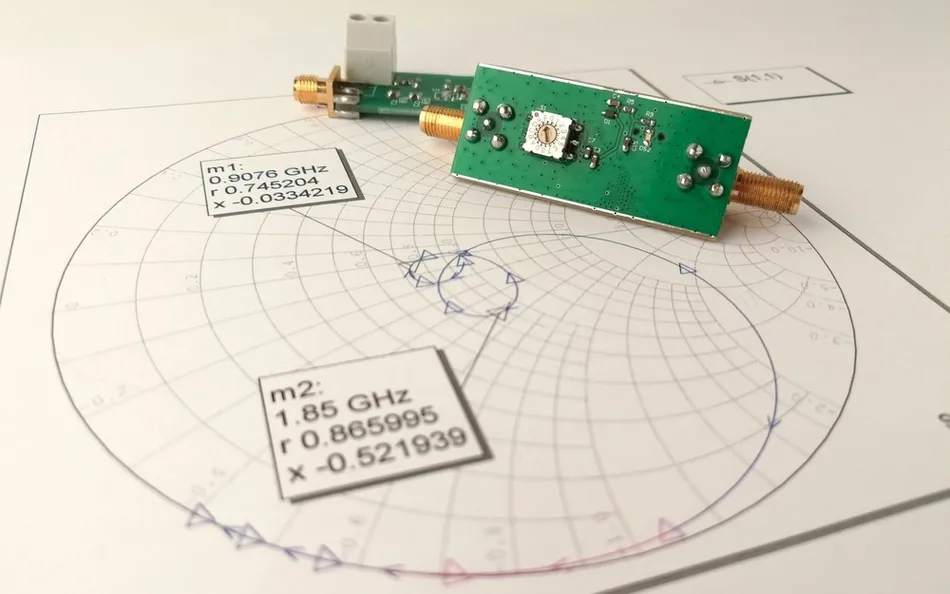
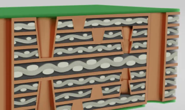
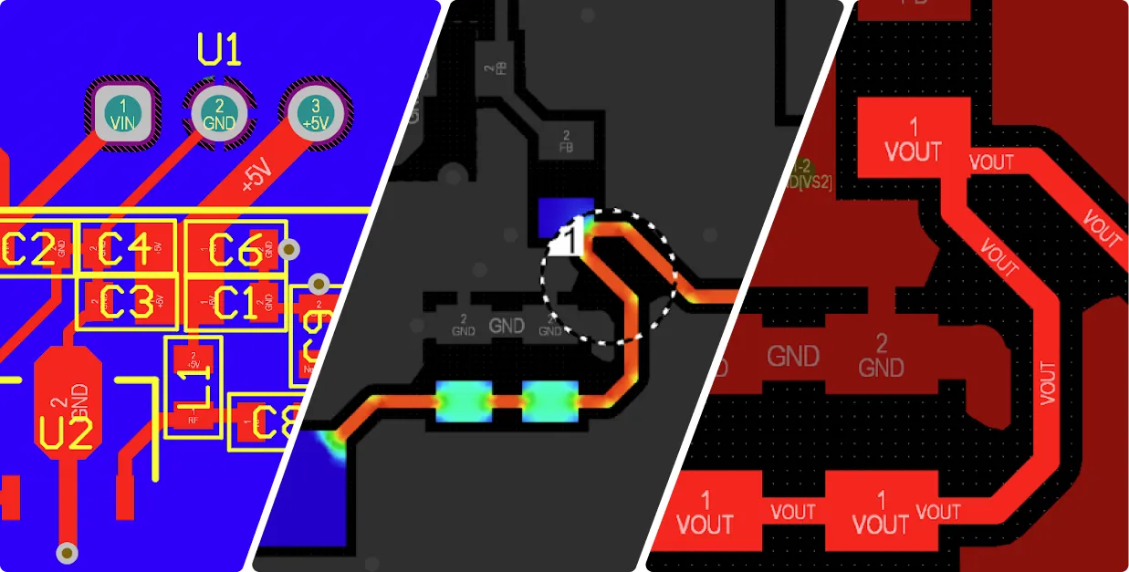
Latest Blogs
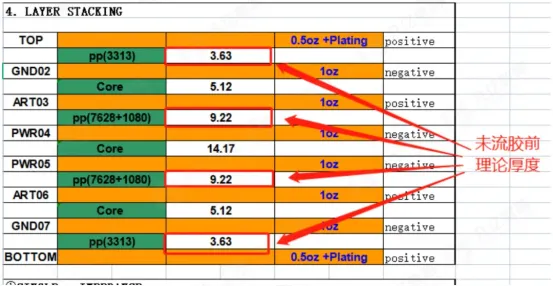
How PCB Copper Thickness Affects Current, Heat, and Strength
PCB copper at 17.5 μm, 35 μm, or 70 μm sets current capacity, heat spreading, and stiffness. 2 oz adds weight, cost, and resin squeeze-out in fabrication.
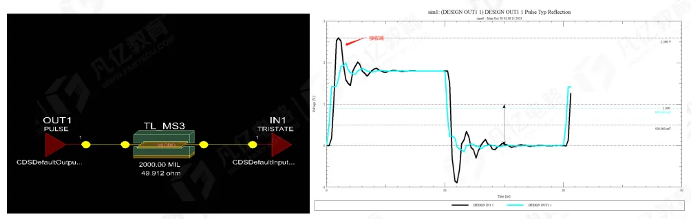
Why a Series Termination Resistor Must Sit Next to the Driver
33 Ω series termination on a 2000 mil line works at the source. Offset of 500 mil adds ripple; mid-line or receiver placement leaves clear signal reflection.
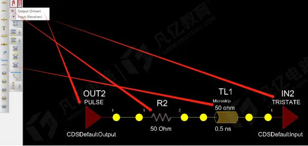
What a Series Resistor on a PCB Signal Trace Actually Does
A series resistor near the driver matches source impedance to a 50 Ω line. Simulation from 0 Ω to 50 Ω shows 30 Ω cutting overshoot; DDR ODT covers data nets only.
PCB Impedance Calculation for Signal Integrity
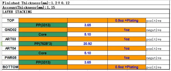
Calculate PCB impedance in SI9000 using stack-up H1, Er, copper weight, residual copper, FR-4 and Rogers data, and a 6-layer 50 Ω / 90 Ω example.
Basic PCB Concepts Needed to Start a Design
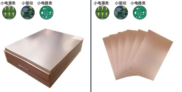
Beginner PCB terms covering FR-4 and Tg, impedance matching, HASL ENIG OSP finishes, core and prepreg, differential pairs, reflection, crosstalk, and blind or buried vias.
PCB Design Pitfalls: Layout, Routing, and Fabrication Details That Can Fail a Board
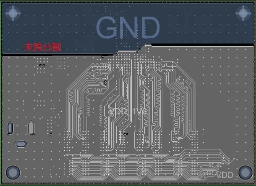
PCB placement and routing pitfalls: isolate HV from signals, keep crystals and decoupling close, avoid split-plane crossings, match differential length, and prevent tombstoning.
15 PCB Layout Techniques for EMC Control
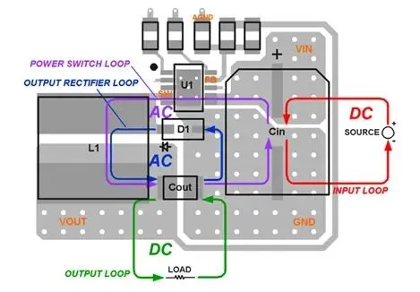
Fifteen PCB EMC layout methods: minimize loop area, length-match differentials, keep power next to ground, split DC-DC loops, match impedance, and add supply filtering and ESD protection.
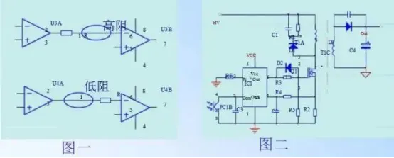
PCB Design Guide: Safety Spacing, EMC, Thermal Design, and Process Details
PCB design rules for creepage and clearance, EMC placement, current-based trace width, single-point grounding, thermal relief, wave-solder orientation, and fiducials.
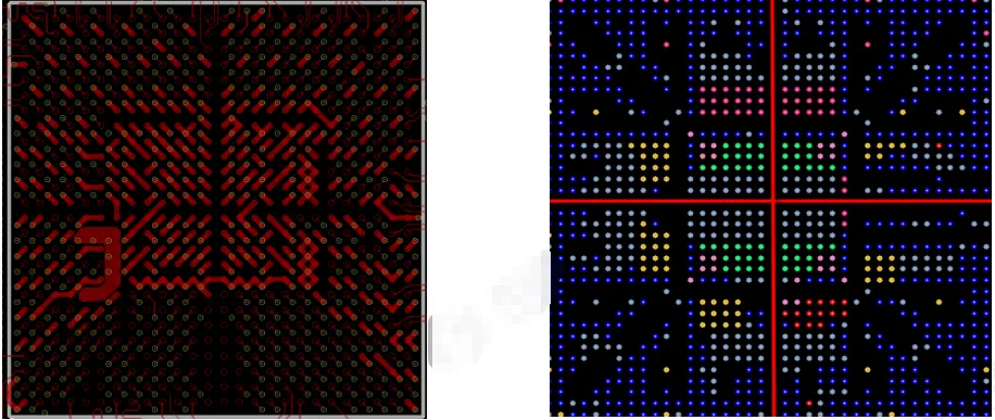
PCB Via Fanout Details That Are Easy to Miss
Via fanout rules covering 8/16 to 12/24 sizes, 1 mm pitch, BGA cross channels, capacitor vias, board-edge GND, differential return vias, and two-pin via sharing.
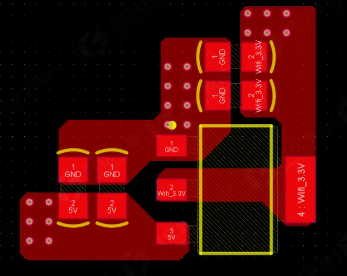
LDO Power PCB Design: Layout and Routing That Keep the Loop Small
LDO PCB practices: in-line or L-shaped placement, large-then-small capacitors, current-rated traces and vias, via order around filters, and a continuous input-output ground return.
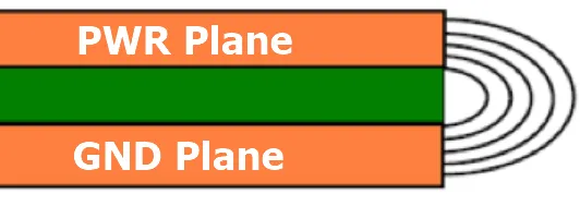
Why the Power Plane Should Be Smaller Than the Ground Plane
Why power planes are pulled back from ground using the 20H rule to cut edge EMI by about 70%, when 100H confines ~98%, and when a 1 mm inset is used on real boards.
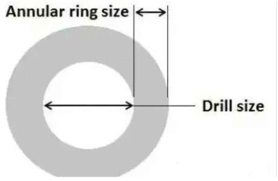
Padless Holes on a PCB: Why Designers Remove the Annular Ring
Why high-density PCBs remove annular rings on unused layers for BGA escape routing, plus via-in-pad, back-drilling, HDI density gains, and reliability risks after reflow.


