










 02:22
DFM For PCB
Design for Manufacturability (DFM) is a critical aspect of PCB development that ensures designs are optimized for efficient production, minimizing errors, costs, and time-to-market. In the realm of electronics engineering, DFM For PCB focuses on guidelines and strategies that bridge the gap between innovative circuit design and reliable manufacturing processes. Whether you are an experienced PCB designer troubleshooting production issues or a newcomer aiming to create prototypes without costly revisions, understanding DFM principles can significantly enhance your project's success rate. At its core, DFM For PCB involves evaluating design elements such as component placement, trace routing, layer stacking, and material selection to align with manufacturing capabilities. Common challenges like insufficient clearances, thermal management oversights, or incompatible fabrication tolerances often lead to defects during assembly. By incorporating DFM best practices early in the design phase, you can avoid these pitfalls, improve yield rates, and ensure compliance with industry standards like IPC-7351. For instance, adhering to rules for via placement and solder mask design not only reduces rework but also facilitates automated assembly lines, making it invaluable for high-volume production or complex multilayer boards. Our articles under this tag provide practical insights into implementing DFM techniques, from selecting appropriate board materials to conducting thorough design rule checks using tools like Altium or KiCad. You will find step-by-step guidance on optimizing layouts for wave soldering, reflow processes, and panelization, along with case studies demonstrating real-world applications in consumer electronics, automotive, and IoT devices. Delving into these resources equips you with the knowledge to refine your PCB designs, ultimately leading to more robust and economical outcomes in your engineering endeavors.
Video Guide


Technical Articles
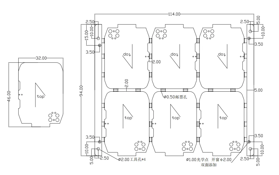
PCB Edge Rails: What CAM Reviews in Panelization Before Production
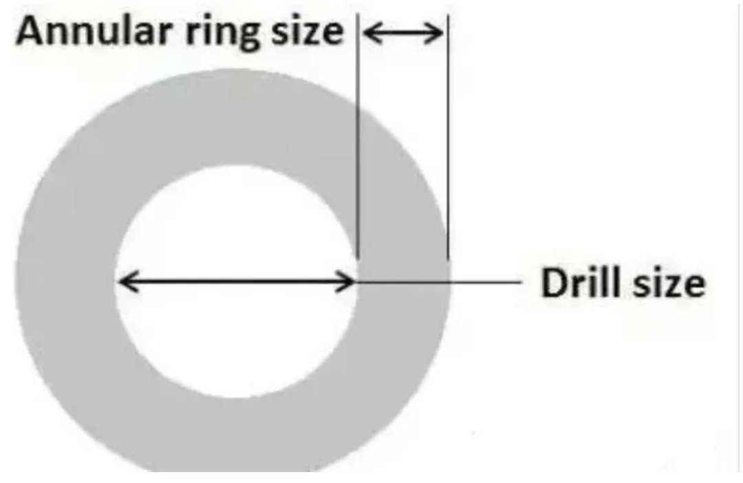
Padless Holes on a PCB: Why Designers Remove the Annular Ring
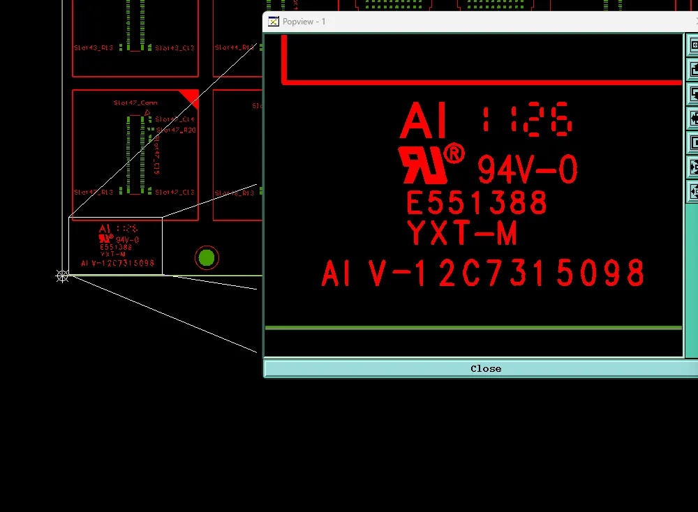
PCB UL Marking: What CAM Needs to Confirm Before Production
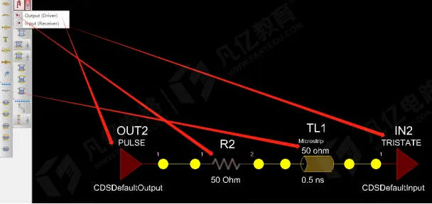
What a Series Resistor on a PCB Signal Trace Actually Does
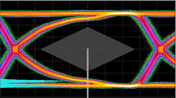
High-Speed PCB Design: From Signal Integrity to Transmission-Line Basics

PCB Design Keep Going Wrong? 13 Key Fundamentals That Build a Solid Baseline

Can a 0 Ω Resistor Really Be Used as a Jumper? A Trap Many Engineers Have Hit
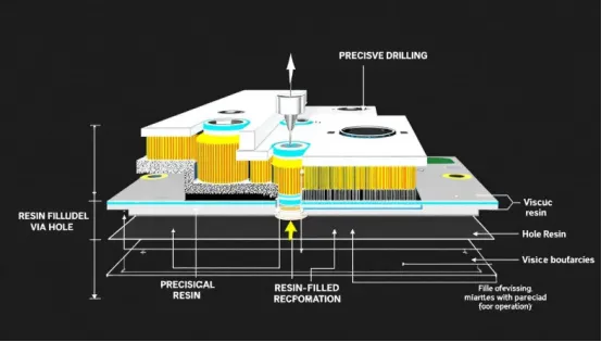
Which Vias Need Resin Plugging? Real Engineer Questions from Production
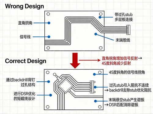
Signal-Integrity Simulation: Five Places Designs Usually Break
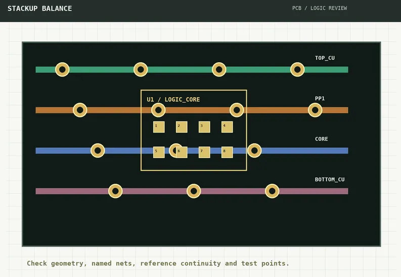
Why a PCB Still Warps When Copper Thickness Is the Same but the Stackup Is Asymmetric

Why Traces Can Still Open After Teardrops Are Added to Vias

Why Backdrill Stubs Can Still Be Too Long After the Layer Pair Is Correct
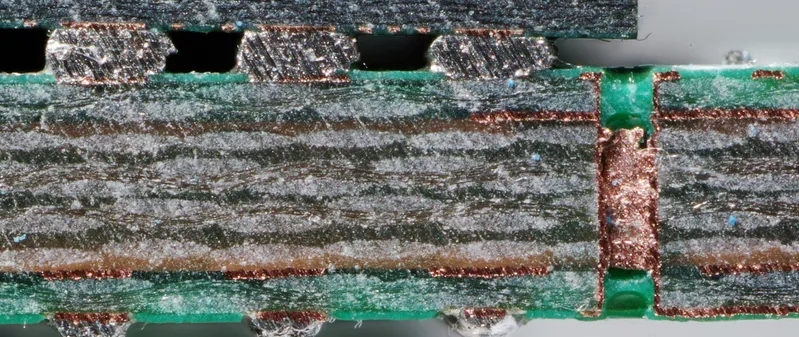
Small Anti-Pads Can Cause Unconnected Vias to Short
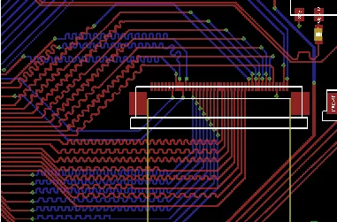
FR4 PCB Differential Pair Routing: Spacing and Length Matching

CAM Confirmation of Fiducial Marks on a 205 × 20 mm 6-Layer Rigid-Flex Panel
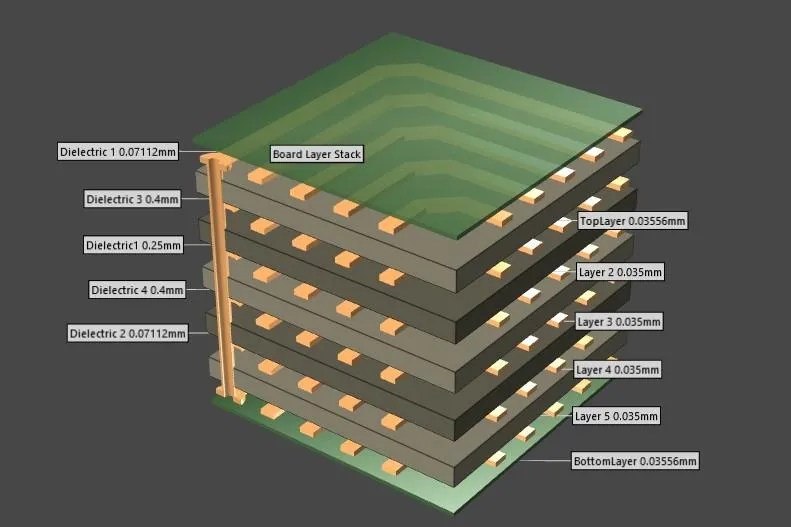
Multilayer PCB Layout Guidelines: Routing, Planes and Layer Management

Multilayer PCB Manufacturer Selection: What to Check Before Production

What Is an Eye Diagram and How to Read One?

Multilayer PCB Impedance Control: Design Rules for 4-Layer to 8-Layer PCBs


