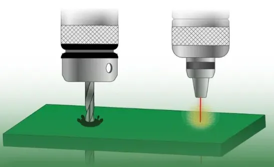
 00:47
PCB Stackup Design
PCB stackup design is a fundamental aspect of printed circuit board engineering that determines the arrangement of conductive and insulating layers within a PCB. This configuration plays a critical role in ensuring signal integrity, managing electromagnetic interference, and optimizing thermal performance in electronic devices. For engineers and designers searching for insights on PCB stackup design, this tag aggregates resources that delve into the principles and methodologies for creating effective multilayer boards, from simple two-layer setups to complex high-speed applications. Understanding PCB stackup design begins with selecting appropriate layer counts, materials, and via structures to meet specific project requirements. Key considerations include controlled impedance for high-frequency signals, power distribution planes to minimize noise, and ground layers for shielding. Practical applications span industries such as telecommunications, automotive electronics, and consumer gadgets, where poor stackup can lead to issues like crosstalk or signal degradation. Best practices emphasize simulation tools for pre-layout analysis, adherence to manufacturing constraints, and iterative testing to refine designs, ultimately reducing prototyping costs and time to market. Articles under this tag offer detailed guides on topics like symmetric versus asymmetric stackups, the impact of dielectric constants on performance, and strategies for high-density interconnects. Whether you are troubleshooting a current project or planning a new one, these resources provide actionable steps to enhance your PCB designs. Dive into the collection to find case studies, tutorials, and expert tips that align with real-world challenges in electronics development.
Video Guide

Technical Articles

4-Layer HDI PCB Engineering Review Case: Stackup Deviation, Countersink Hole Depth, and Material Availability Challenges
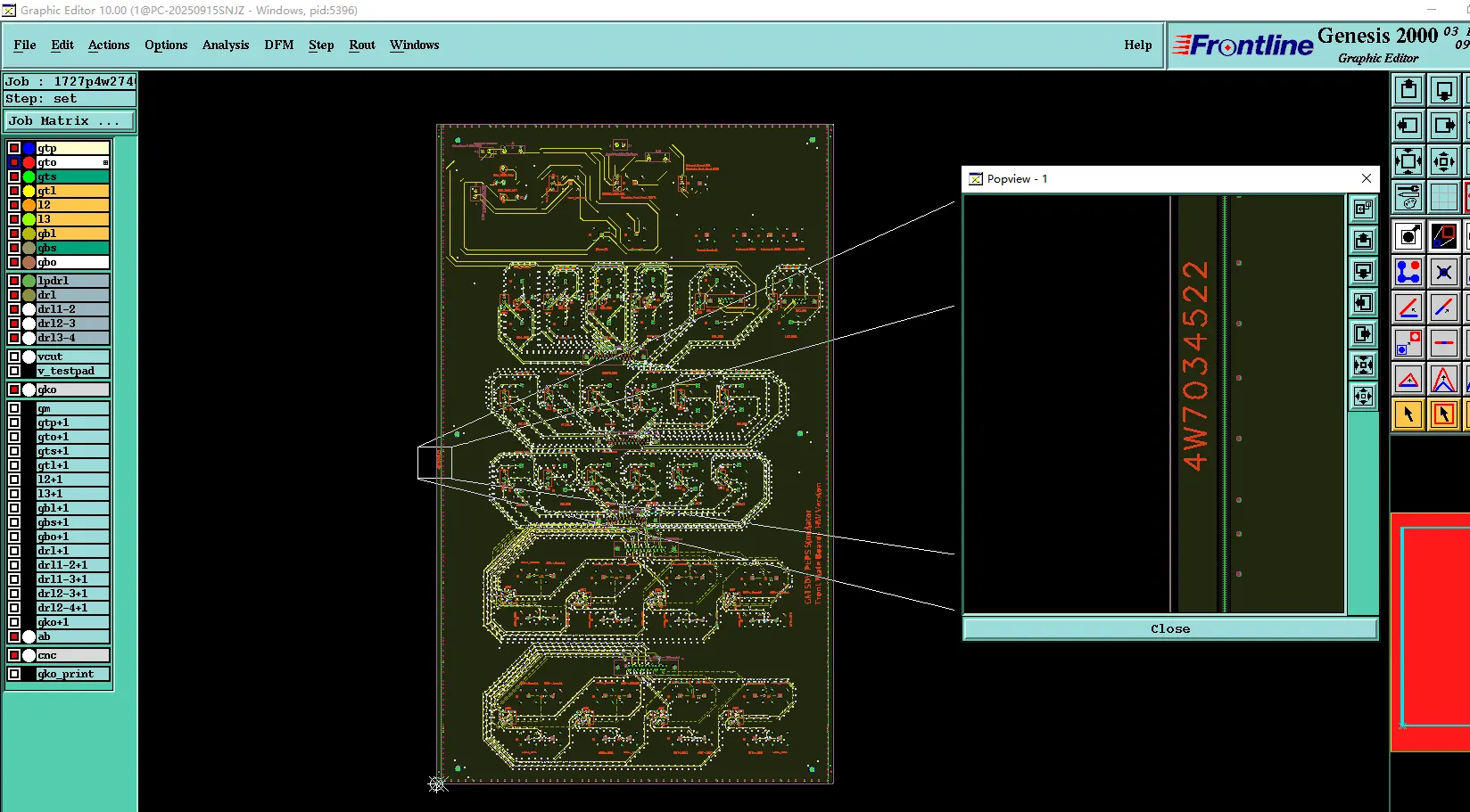
Engineering Case Study: 4-Layer FR-4 PCB Blind Via Optimization and Multi-Layer Drill Overlap Resolution During CAM Review
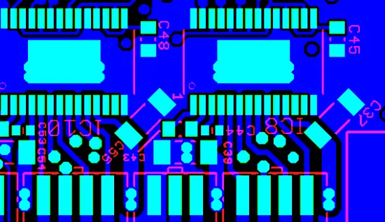
4-Layer FR-4 PCB CAM Review Case: Stackup Adjustment, Silkscreen Clarity, and Process Edge Copper Balance

How to Avoid Common Rigid-Flex PCB CAM Issues in Sensor Applications
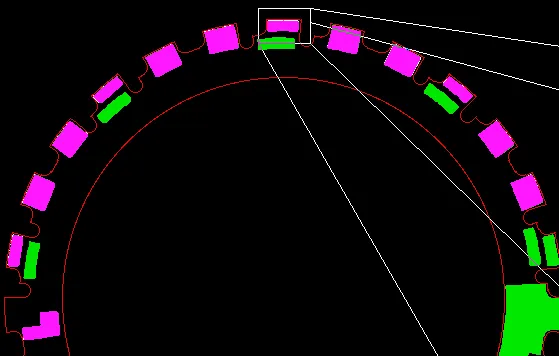
4-Layer 6oz Heavy Copper Motor Stator PCB Engineering Case Study: Addressing Edge Clearance, Small Hole Positioning, and Data Inconsistencies in CAM Review
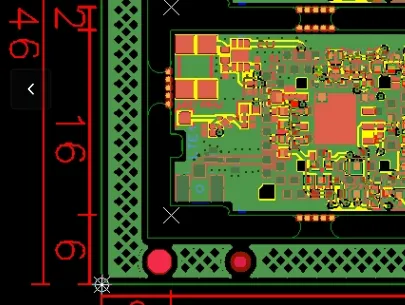
Rigid-Flex PCB CAM Challenges: Transition Geometry, Via Clearance & Stackup Issues
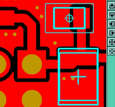
4-Layer High-TG PCB Stackup, Panelization & Mask Issues Fixed
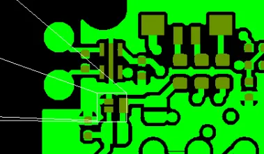
Resin Filled Via & Blind Via Issues in 6-Layer 2nd Order HDI PCB CAM Review
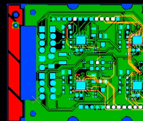
How to Prevent Warpage in 4-Layer 2oz FR-4 TG170 PCB with Proper Stackup and V-CUT
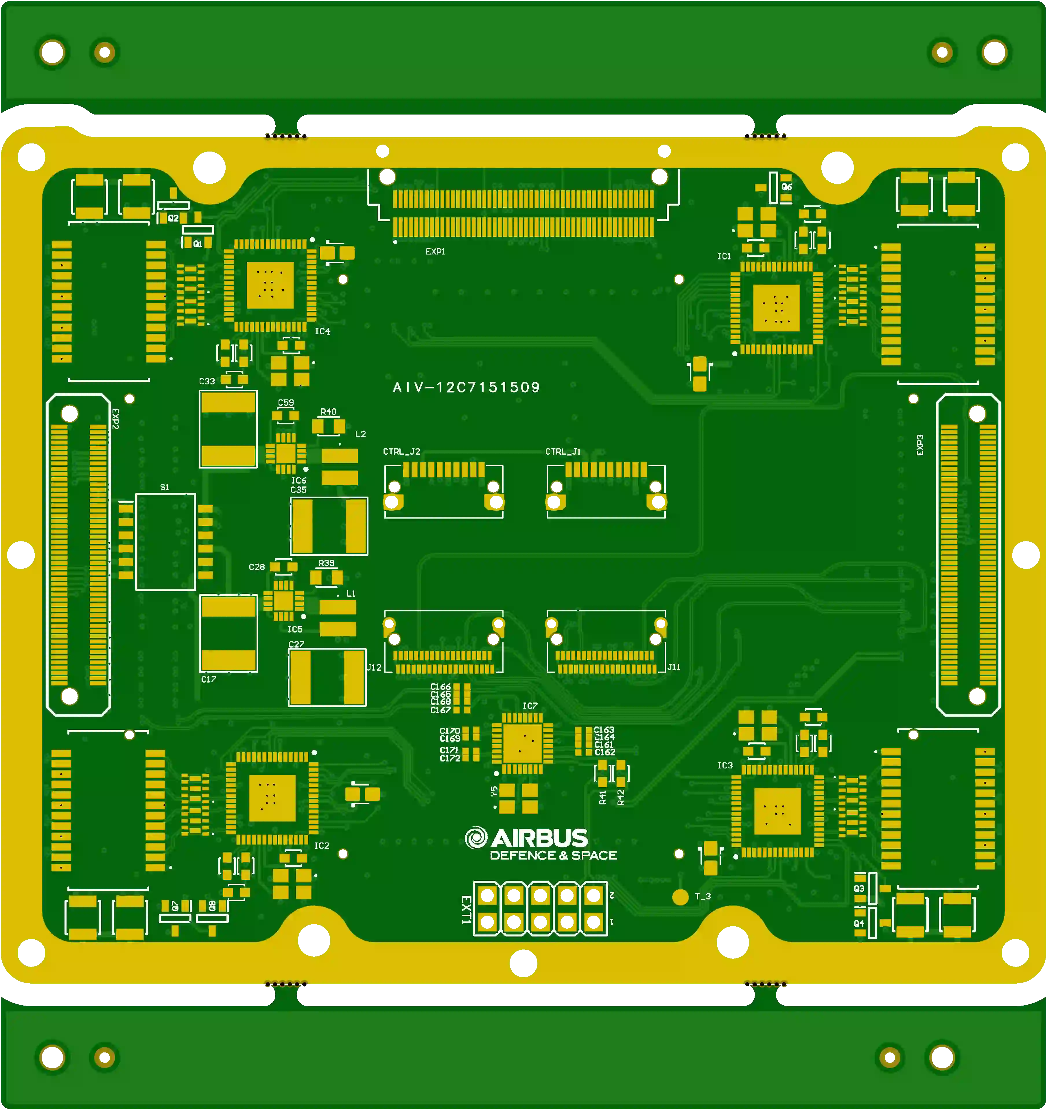
12-Layer High-Density PCB Review: Stackup, Annular Ring & Edge Copper Issues
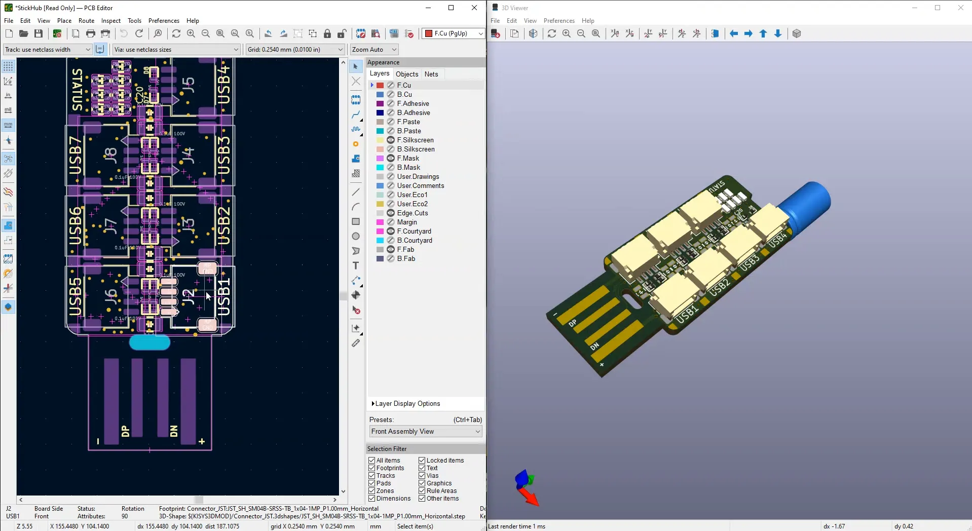
KiCad Ecosystem Explained: Tools, Libraries, Plugins, and PCB Manufacturing Resources
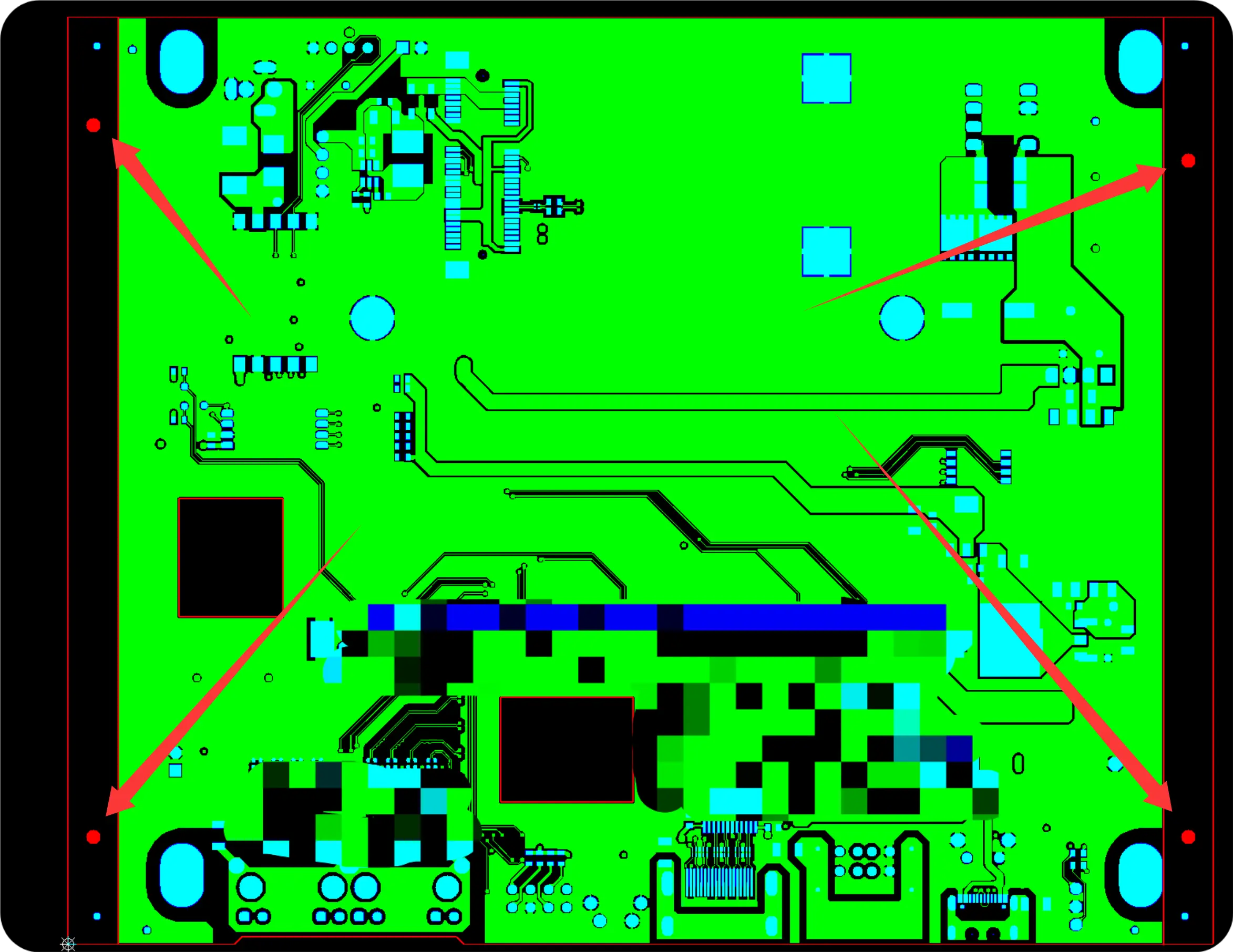
Handling PCB Impedance Trace Width Adjustment in DFM Review
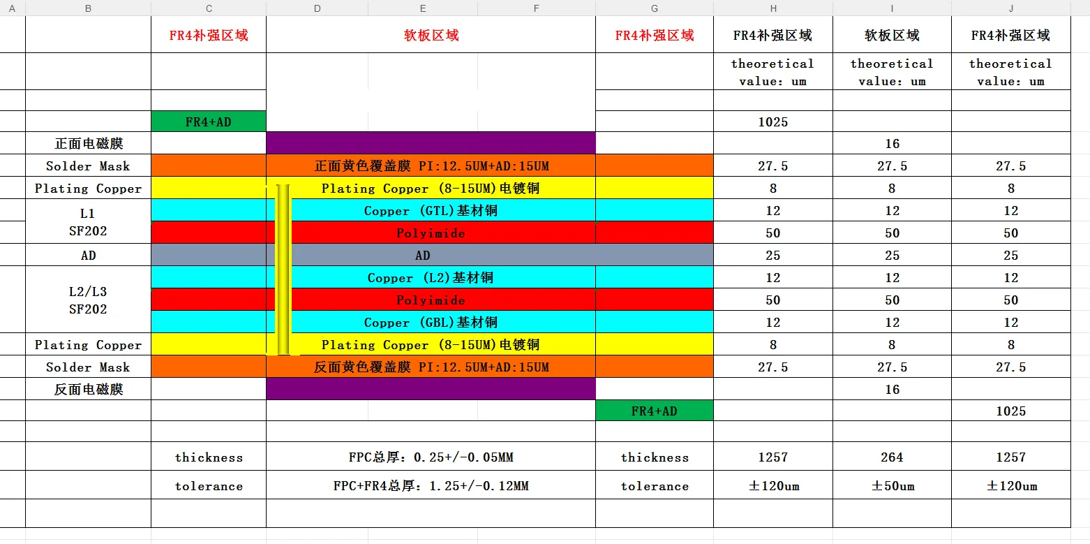
FPC Stiffener Design Rules: Avoiding Common DFM Roadblocks
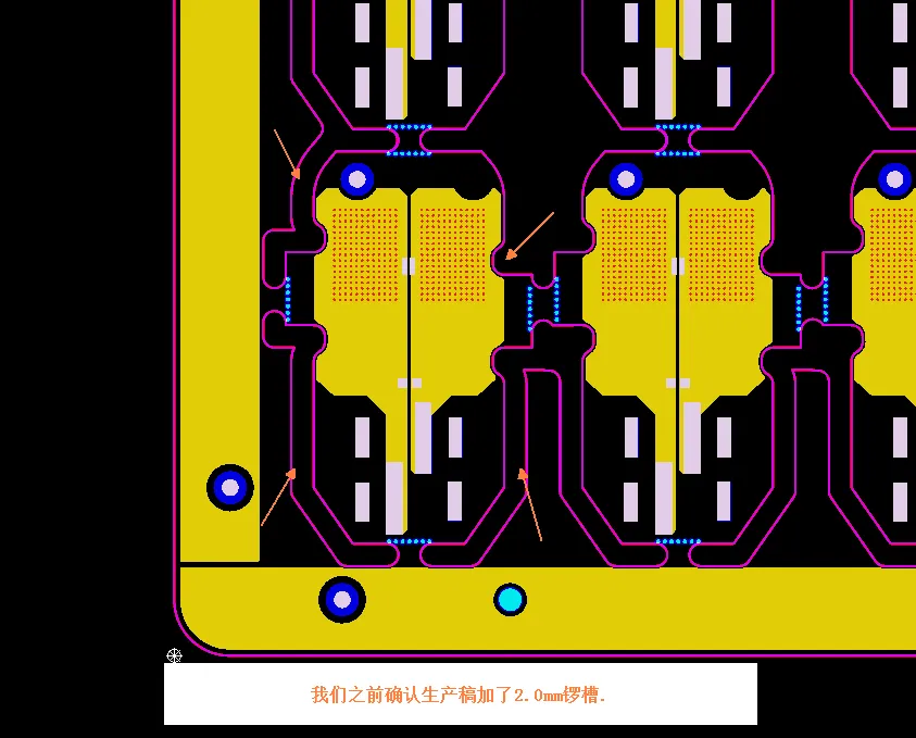
PCB Panelization Slot Design: Why Your Gerber Needs Routing Paths
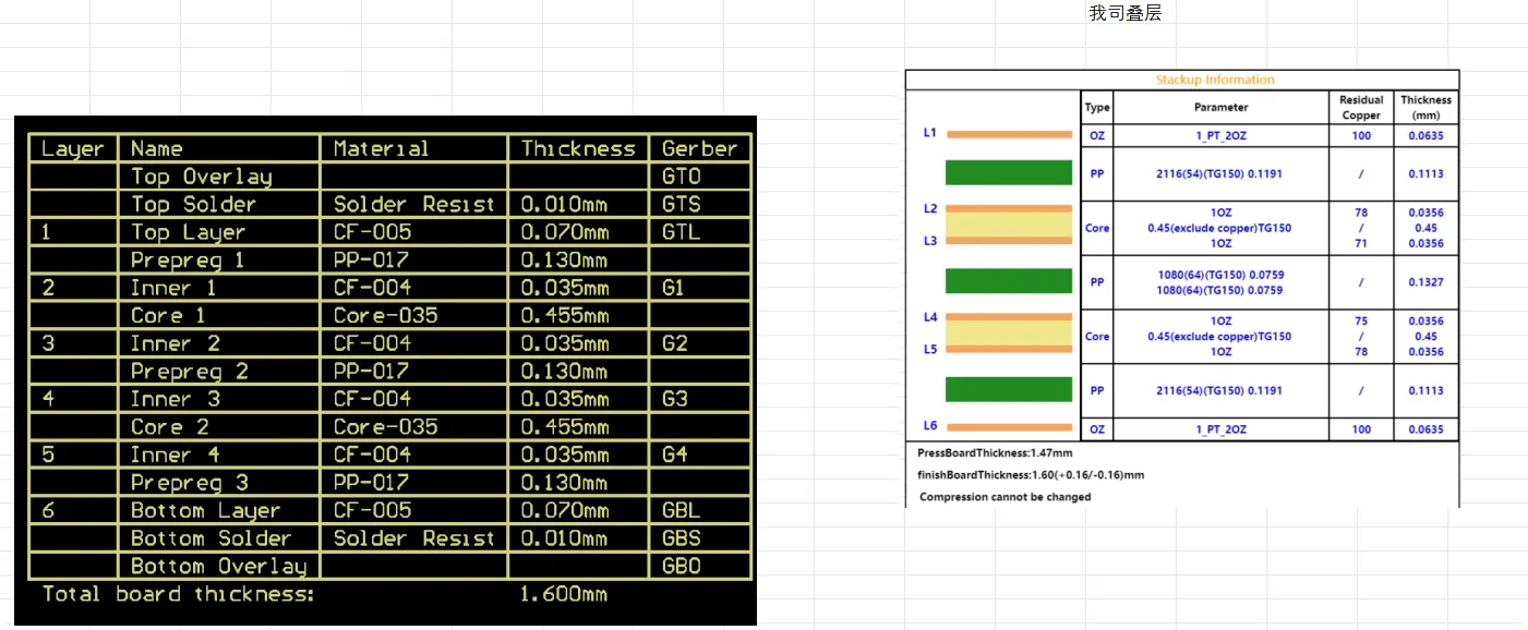
PCB Stackup Adjustment for Reliable 6-Layer TG150 Production
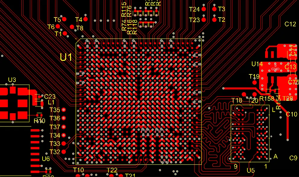
HDI Gerber Checklist Before Sending to Your PCB Manufacturer
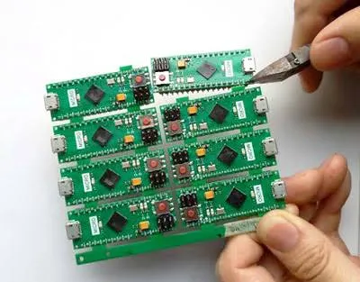
HDI Panelization Design Mistakes That Increase PCB Cost
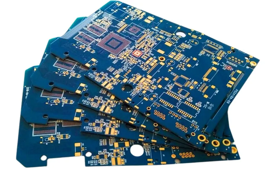
Common Via-in-Pad Design Mistakes in HDI PCB
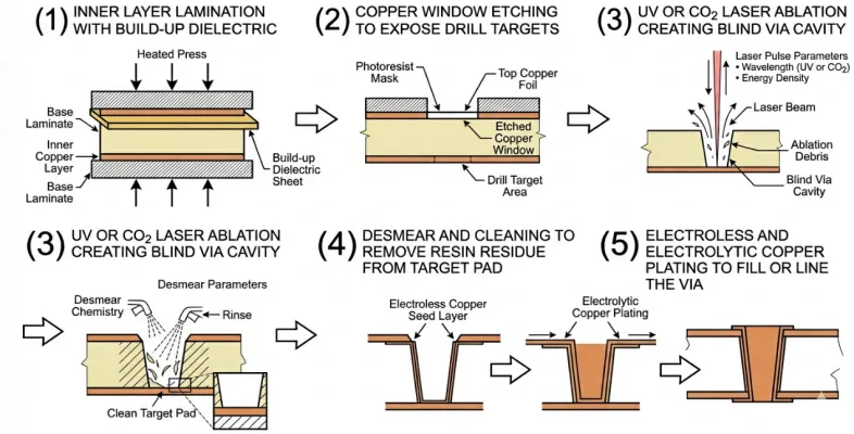
HDI Laser Drilling Mistakes That Affect Manufacturing Yield